Quantcast
Channel: Bobs XK120 Restoration
Viewing all 34 articles
Browse latest View live

POST 33 - JULY 2012 - PROGRESS 1 - FUN 5

$
0
0
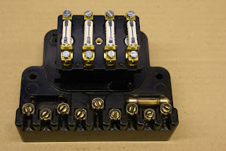
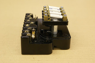
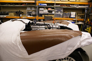
Cylinder Head, Compression Ratios and Gasket Choice
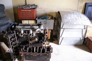
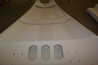
After a few hiccups relating to shims, I finally feel happy with my cylinder head assembly.  The waterways have been welded up and re-machined with 18 thou skimmed off to clean it up.  Inlet and exhaust faces have had a light skim to ensure absolute flatness.  New hardened seats and phosphor bronze guides have been fitted along with stainless steel valves and new springs.  The camshafts were in excellent order and just needed a light clean up and new bearings.  So all in all, a pretty comprehensive head overhall.
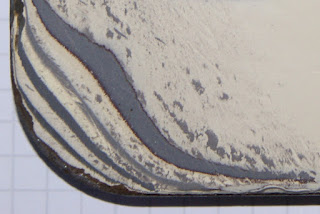
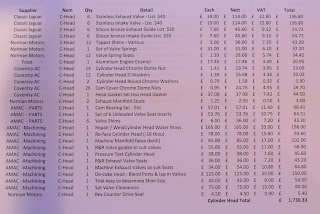
Time to decide on the ideal compression ratio and consequent gasket thickness, with a wide range available, from the original 15 thou, all the way up to special order composite items at 130 thou.  First I need to re-establish head chamber volume after machining.  I did this exercise previously by using liquid paraffin, establishing its specific gravity and weighing it on letter scales.  All chambers came out at between 105 and 107cc which I thought a little high but surprisingly the C/R came out about correct at 8:1 on my spread sheet.
This time I did the same exersise using a 100cc burette and water (as I subsequently discovered that the SG of liquid paraffin is not absolute) and they came out at around 95cc. 

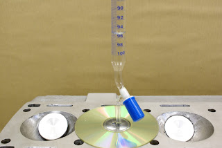
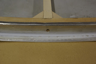
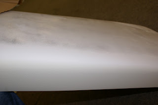
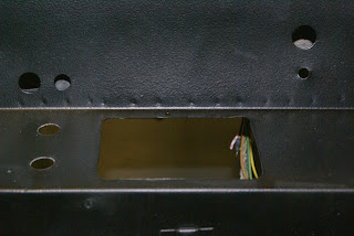
No more make shift measuring.  A proper burette and a clear DVD
stuck down with a smear of grease.  The head was first set exactly
level to avoid surface tension bubbles under the plastic.

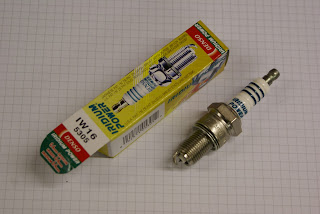
To acheive my ideal 8.5:1 C/R my spread sheet indicated that I required a gasket of around 90 thou and Rob Beere racing had a Cometic 98 thou composite item in stock.
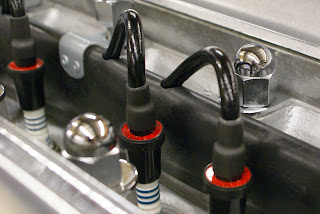
Delivered the following day it was fitted and the head duly torque'd down to 60 foot pounds 
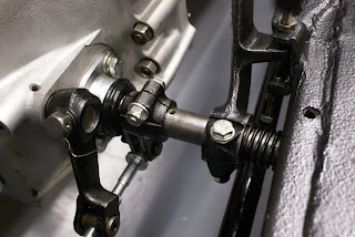
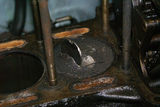
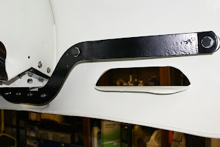
PROBLEM

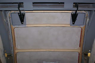
No matter how hard I tried, and how carefully I positioned the tensioner, one or the other sprockets would not go over the end of the camshaft indicating too thick a gasket or too short a chain.   I had, as a matter of course previously checked the chain length against the original with no discernable difference.  The shortfall was nothing more than at most a frustrating millimeter or so, indicating a gasket thickness reduction of half that (as the chain goes around two sprockets) - around 20 thou.  Again consulting my spread sheet, going down to 60 thou would produce a C/R of just over 9:1 not my absolute ideal but easily acceptable.
More on the final outcome in my next post.

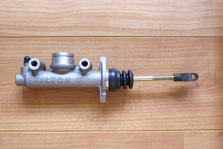
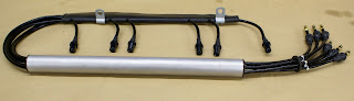
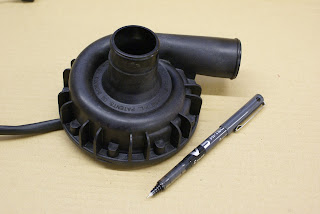
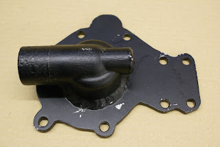
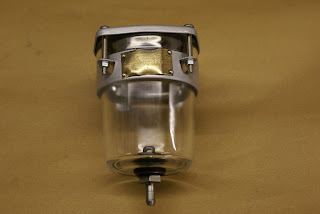
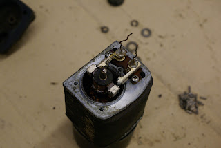
Dynalite - an alternator that looks like a dynamo
I spent quite a while researching this and finally concluded that it was a worthwhile upgrade, producing a maximum of 40 amps and wieghing 10 pounds (the original Dynamo wieghs 19).   The alternative was to buy the bracket and pulley plus a cheap scrap-yard alternator.  It would doubtless have saved a considerable sum but the essential pulley only comes as part of an upgrade kit, with no supplier prepared to sell it on its own. 
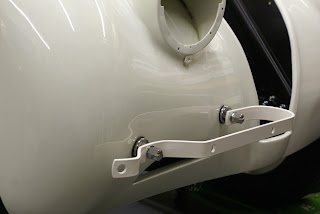
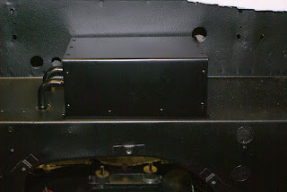
The dimensions of the Dynalite are identical to the dynamo and I added the finishing touch by fixing the original  "Lucas Special Equipment" plate and faux rivets to the body.


Adding the Lucas plate has probably voided the guarantee!

Morgans Diary
Anyone wanting to know what's happening on the Classic Car scene in the North of England buys Morgans Diary in February, which lists pretty comprehensively every event for the year.  It's also used by organisers to avoid clashes with other events.  So how did this super useful publication come about?
Many years ago before the internet, Mr Morgan started to keep a list of dates for Classic Car events, Auto-jumbles etc. in the North of England and word got around that he was the man to ask if you were planning an event or looking for something to do at the weekend.  After a while he formalised his lists into a small printed publication and sold copies, with the proceeds going to charity - Good Bloke. 
It's popularity grew to the point where it was almost a full time job for a single individual and Mr Morgan decided he had done his bit and it was time for someone else to take up the reins.
Step up to the plate Tony Raylor and York Vikings Rotary Club - with many volunteer hands to make light work of the job.  Morgans Diary (Now officially called Morgans Guide to Historic and Classic Vehicle Events) has raised to date an amazing £150,000 for charity and recently handed over £10,000 to The Great North Air Ambulance.
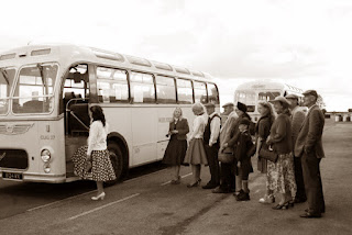
For a publicity shot they needed an appropriate Classic car as a link and as I had the time and live reasonably close to Tees valley Airport I was both happy and honoured to oblige.

Rotary Chairman Martin Kirby hands over a Cheque for £10,000
to Great North Air Ambulance Paramedic Dave Allanby

Raby Castle - JDC Area 11
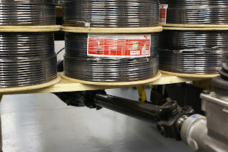
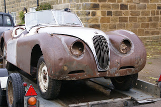
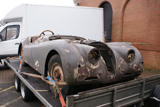
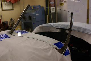
The lack of overall progress in the past two weeks has mainly been down to a very busy schedule of shows and trips with no work taking place over any weekends in June.
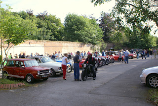
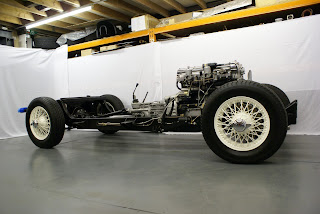
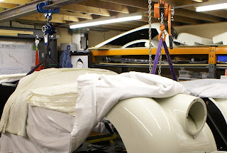
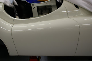
June 24th was JDC Area 11's main annual event at Raby Castle.  As an added attraction we decided to take my rolling chassis along.  It created a huge amount of interest and it was gratifying to hear dads explaining to their kids the purpose and function of the various parts, normally covered up.

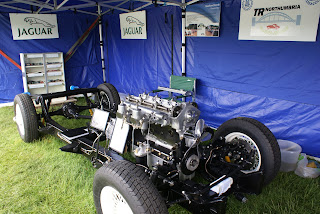
120 Rolling Chassis on display at Raby Castle  June 24th
Also on display were a couple of couple of cars borrowed from Jaguar Heritage and used in films,
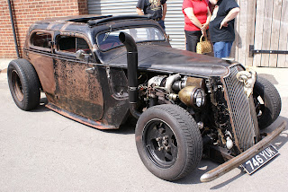
the Mike Myres Union Flag painted "Shaguar" and an XK8 from the Bond Movie, Die Another Day, with a Gatling type gun mounted on the back.


Couldn't miss this photo opportunity
As I wasn't going to get the chassis back until the following Wednesday I took the opportunity to freshen up my workshop and give the floor a coat of paint.


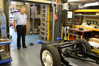
Mr G M wisely removed his shoes before entering.

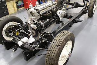
Safely back home.  Shame about the sheep Sh--- in the tyre treads
The following Saturday JDC organised a visit to the North Yorks Moors Railway Workshops at Grosmont which involved a drive through some of Englands most deserted roads, with fantastic moorland views.   Just as well I forgot to take my camera.  This post would otherwise be never ending with pictures of hills and Steam Trains.

Hob Hole near Westerdale - Superb "exactly as shot" composition
 by Geoff Mansfield with only a few seconds to set up.

Next post mid July


POST 34 - CONVERSION TO HYDRAULIC CLUTCH - OR NOT

$
0
0
Hydraulic - V - Mechanical Clutch Operation
I had every intention of converting the clutch from mechanical to hydraulic operation and to that end purchased a 150 slave cylinder with mounting bracket. The bracket did not exactly fit the 120 bell housing and required a fair bit of fettling to get the push rod moving at something like the correct angles when moving the clutch operating lever. It did eventually all line up reasonably well but looked like a bodge, as if it was never meant to be there.
This just doesn't look right
To resolve the master cylinder issue, I had considered fitting a complete new pedal box but at 5 foot 8 inches tall, and with bucket seats fitted, the original pedal location, for me, should be just about right.  The current trend to move the pedals forward a couple of inches, which a new pedal box would allow, might increase the cars future saleability.  (I remember reading somewhere that tall men are generally richer than short men).  Having to put blocks on the pedals as my dad did on my first bike seems like a naff idea, and I am after all building this car for me. 
So, having acquired a likely master cylinder some time back, I set about looking at how to best utilise it in conjunction with the existing pedal arrangement.  With the new slave cylinder fitted, there is no longer a place for the end of the clutch operating shaft.  This can possibly be resolved by making up a substantial plate with some form of bearing for the remote end of the cut down shaft.  Also, the operating lever will need to be relocated with a new key way machined into the shaft and the chassis will need some holes drilled to attach the plate.  It's all getting horribly complicated.

Time to ask the obvious question.

Why exactly do I want to operate the clutch hydraulically?
Whilst the mechanical arrangement has lots of parts, it is in fact reassuringly simple with very little if anything that could fail catastrophically. 

As usual with Jaguar design, many parts make up the clutch
operating mechanism.  Note washer in bottom right hand
corner and see "whats that clicking noise" below.
My 140 has exactly the same arrangement and I have never thought it heavy to operate.  With a 9.5 inch E Type pressure plate it will be lighter anyway.  No seals to worry about and no hoses to split.  Nothing to bleed and no fluid to periodically check and top up and wonder where it went.  On the other hand, the idea of having a shaft mounted between one fixed point, the chassis, and one vibrating point, the engine, can not in principle be good.

Very odd ware characteristics on end of clutch shaft, bearing and cup.
Looking at the wear patterns on the bell housing end of the shaft, spherical bronze bearing and cup, it clearly has not had a happy life.  Never the less, it was still working (as far as I could tell) after fifteen years of hard use and neglect and a further forty five years of miserable lonely inactivity.
On balance, it's clear that the right and proper thing to do is to restore it to its original mechanical state, rotating happily in new bronze bushes, carefully lapped into their cups and then lubricated with very best grease that money can buy.    Why did I ever think it a good scheme to usurp this fine piece of engineering with masters, slaves and their vile corrosive hydraulic fluid.  Whilst on a roll so to speak, perhaps I should consider upgrading the braking system with cables, rods and levers!
My good friend Richard Cook who fortunately understands my passion for such things, machines the badly worn end of the shaft and fits a sleeve making it as good as new.  Medical science has some catching up to do.

Resplendent with new sleeve, bush and cup.  What more could
an original clutch operating shaft want?

So I guess the only remaining question is :
Is there anyone out there who would like to buy a brand new Tilton 74-700  7/10" Master cylinder kit complete with remote mounting kit, hoses and clips and an XK150 slave cylinder with slightly butchered mounting bracket.

Mr Happy Shaft back home and back in employment.

Tilton Master Cylinder - Heading for EBay

Whats that clicking noise?
Pushing the clutch pedal on my 140 would often but not always produce a light clicking noise which could be felt through the pedal. As it came and went, I was never too concerned.  Last winter I decided to investigate and removed the whole clutch shaft assembly, cleaned it, replaced the bearings, "O" rings etc. and re-assembled it. The result was a satisfying silence. The noise had gone, for about a week, then it re-appeared. With assistance and a listening tube, I established that the noise emanated from inside the chassis. The end of the spring had worn and worked its way into the chassis side, sometimes catching and winding up then twanging free with the shaft motion. It seemed strange that nothing was fitted to the shaft to stop this happening.  About this time I bought Bernard Viarts amazing book - Jaguar XK140 Explored.
Bernard Viarts amazing book on the 140 and a typical drawing.
A 120 edition is hopefully due out later this year

The superb drawing of the clutch shaft assembly, although for a left hand drive car, shows a washer (C3295) between the spring and the chassis.  Definitely not present on my car and very unhelpfully not shown on plate F of my Jaguar parts manual.  I found a suitable washer and did a trial fit.  Removing the shaft to fit the woodruff keys, the washer fell off the end and into the chassis.  My 'magnet on a stick' fished around inside the chassis and was carefully removed with not one, but two washers attached!   It doesn't matter which way you remove the shaft, the washer will most likely fall off into the chassis.  Consequently, you would never know it was ever there, and the parts manual nicely confirms its non existence.

Prop Shaft angle
The new prop shaft to fit the T5 box finally arrived and was fitted, but the angles required by the UJ's to meet the diff seemed a bit severe. The reason of course was that the re-tempered springs are sitting high with very little weight to settle them. I calculate that a full fuel tank, rear part of the body with boot contents and the best part of two passengers would approximate to 200Kg's.
Fortunately I have to hand a pallet of coaxial cable with each 250 Mtr reel weighing about 11Kg. Stacking 18 reels over the axle settles the springs very nicely and makes the prop shaft angles acceptable.
18 reels of coaxial cable approximately equates to the back half
of the body, a full tank of fuel and a couple of big lads.
Springs and prop shaft angle now look about right

Cylinder Head and Gasket - Final solution
Following on from my previous post and the problem of fitting the camshaft sprockets, assuming my calculations are correct, it looks like I will have to settle for a thinner gasket and a compression ratio of 9:1.   Rob Beere supplied another Cometic composite gasket, this time 60 thou, and it all goes back together without a hitch.

Sprockets fit easily to cams with gasket reduced to 60 thou.
Why has the head got this odd double stamped engine number?
See post 10 for the most probable explanation.
It's still a puzzle as to why, with only 18 thou being skimmed of the head the chamber volume was reduced by around 10%.  One possible explanation could be the depth of the new valve seats and the profile of the valve top, but I don't have another head to compare.  Another explanation could just be that my calculations are rubbish.

Could valve seat depth and profile be responsible to reduced chamber volume?
As I intend to use a 123 Ignition set up with programmable advance curves via USB port and lap top, I am hoping that this is all a bit less critical and I will have the opportunity to tweak the timing to accommodate the higher ratio. With 99 octane costing around £1.40 a litre (that's around $8.30 a US Gallon to you hard done by American boys) and not available at many petrol stations, you can see why it would be good to be able to use 95 octane.  I know that the theory says 99 gives you a bigger bang so you should use less of it, but in my experience it seems to make little if any difference.

Miscellany - related topics

Beamish Rally
A couple of weeks after this wonderful day out, I received a phone call from Mr George Jolly, the event organiser to tell me I came first out of around 150 entrants.  Totally unaccustomed to winning anything ever, this came as very nice surprise.  However, the actual credit for the win must go to navigator Tony Firth, who has an encyclopedic knowledge and recall of all things relating to old motors, no doubt giving us a super high score for the quiz part of the rally. 

Stuffed again by the weather men.
The biggest classic car event in North East England at Newby Hall near Ripon was cancelled after a "pitch inspection" four days prior to the event.  No doubt the forecast of a further twenty odd hours of heavy rain over the next three days would have played some part in the decision.  Apart from the occasional light shower on Friday, the forecast was around 95% wrong.

Next Post beginning of August


POST 35 AUGUST 2012 NO MORE BOOT LID BLUES

$
0
0
The saga of the boot lid could fill a couple of books all by itself.  To recall.
It was missing along with many other parts when I bought the car back in 2010.  I did eventually acquire one which had had the bottom third of the ash frame replaced, but when offered up to the car, the overall shape was wrong.  I returned it to the supplier along with profiles cut from hardboard showing the exact shape required.  It was duly reworked and returned and a trial fit confirmed that it was now fairly close to being right.
However, close inspection (a little late in the day I will admit) showed that the aluminium skin was secured to the frame in many places by steel nails. Body shop man Alex was less than happy with this and I was sent packing yet again, booted out, boot lid in boot so to speak to find a solution.
Lid No 1    Less than ideal skin, lots of holes and a few nails.
 I allocated a whole day to resolve this and played around carefully removing the steel nails and replacing them with specially made (by me) aluminium pins bonded into the ash with the intention of welding the heads to the skin. After several hours of prating about, it became very clear that I was pissing in the wind (I apologise for the language but it best describes the mood) and went home.
The following day, a Sunday morning I am back with renewed spirit, take afresh look at mess I've made and decide to do something else instead. 
Contemplating the purchase of a complete new lid at circa £3000, I recall a conversation I had about a year back. A friend of a friend said he may have one but it was probably beyond repair. A couple of phone calls and an hour later I'm in the garage of Rob Hind at Sadberge and looking at a rotten wood frame with perfectly good skin.
If I can fit this good skin to my OK-ish frame that might be be the answer.
Lid No 1    As well as repaired bottom frame, steel strips are rusting
Back at the workshop and further investigation indicates that opening up the wrapped around edges of the skin will be difficult.  I try annealing first but can tell that anything more than slightly opening the seam will end in tears.
I eventually manage to remove the rotten frame from the skin and and determine that it should not be beyond my wood crafting skills to fabricate a whole new frame to fit into it rather than use the repaired one.  This massive misjudgement is dealt with in detail in post 29 (Boot Lid abandoned). 
As outlined in this post, after many hours of wood wasting, I eventually find and order up an exact copy of the original frame for £250.  As requested, it is delivered in pieces enabling me to build it into the skin.  I am now back in my comfort zone and work proceeds apace making up new steel strips to screw onto the frame and slip into the aluminium skin.  The frame is temporarily built up with hinges, handle and catches and a trial fit looks promising.

First trial fit of temporarily assembled boot lid frame looks good
Next I need the aluminium trim pieces to fit around the edges and Contour Autocraft come up trumps again with a really good fitting set.
Having established that the frame is fundamentally the correct shape I prime and refit the steel strips, inject Tiger Seal into the folds then assemble the frame into the skin.  Crimping the skin back in place with a special tool borrowed from Alex was very easy, but the addition of the sealant means almost certainly that it will never come apart again. 

Edge crimped onto steel strip and sealed in with Tiger Seal

Ash and softwood laminated frame match the rear end shape exactly

Back to the body shop and Alex tweaks the fit, bashes it around a bit then skims and shapes it before giving it back to me.  All that's left is for me to glue it all together and fit the corner pieces supplied with the frame kit.  Its finally taken back to Alex who is at last satisfied that once painted, it will look perfect and more importantly stay looking perfect.  My final job will be to fit the inner plywood panel but this will be done from underneath with the boot lid fitted, to ensure that no twist occurs. 

Rare view of boot lid from petrol tank location.  Ply panel will
be fitted from here to ensure no twist occurs.
Once screwed in place this adds an unbelievable amount of stiffness to the whole boot lid structure.
Just for fun I tap into our companies small works costing programme for jobs based on time and materials.  I put in my time spent, material costs and associated travelling - three time to Newcastle and twice to Harrogate.  With an hourly rate of £37.60 a nominal overhead cost and mark up it totals up to £3,267.27  There is a moral in there somewhere. 

Miscellany - related topics

Croft Nostalgia Weekend
Preceding the Croft Classic Weekend I was invited to a Press Day along with a few other JDC members to help promote the event.  It turned out to be a thoroughly enjoyable day with plenty of opportunity for track action and quite well organised compared to last year.  BBC regional News gave it a half minute plug in the evening and my 140 appeared for a nano-second at the back of a bunch of cars on the track and a few seconds later at the front - if only!

The Croft Nostalgia event is a fabulous weekend with all the atmosphere and a good deal of the spectacle of the Goodwood Revival, but without the huge crowds. The BRDC have a full programme of classic racing and everyone has access to all areas including the paddock. At £25 for both days its quite a bargain. No doubt it will cost a little more next year.
Set up 1955 Photo I took end of July at Croft Press day

Trailer mounted Rolls Royce Griffin V12 ticking over. Only a couple
of wheel chocks stop it shooting off down the runway when opened up.
Next Post mid August


POST 36 AUGUST 2012 IGNITION SYSTEM & USB PROGRAMMABLE DISTRIBUTOR

$
0
0
By the end of this month that scary engine start up moment will be imminent with only the exhaust system, cooling and ignition left to fit.


In close to fifty years of driving old cars, I would say that nine out of ten problems I've encountered on the road have been electrical and often ignition related.  Back in the sixties, even brand new cars had problems, especially on cold wet mornings when they were reluctant to start.
With this in mind, I'm keen to ensure that my electrical and ignition installation will never give me cause for concern.  It would also be good to see a pristine 1950 engine bay.  This competing requirement will inevitably result in some compromises, but original HT leads and plug caps would be good.  The downside might be interference to my proposed DAB radio installation, electro magnetic interference upsetting my electronic ignition system or RF noise locking up my neighbour's digital TV's as I pass by.  I really don't know and can't find any one that does, so it will be a case of try it and see.  Fortunately I have access at work to a Spectrum Analyser which will display whatever nasty stuff is being radiated and provide precise data relating to the effect on digital radio and television signals.  I'll let you know the outcome.
Cap, conduit and HT leads not quite as original and needing
some attention
XK's for the first few years had the HT leads routed under the carburettors and around the back of the engine leaving the front uncluttered.  It was not until 1953 that they were routed over the cam cover, possibly for some technical reason or maybe just to save a few pence on a couple of yards of HT cable.  Again, no one seems to know.  As a very early 120 my car would have benefited from that original design and in the absence of any good reason to revert to the later layout I adopt the original route.  To minimise the possibility of cross firing between leads (one of several reasons mooted for the change) I run them in an aluminium tube with a central polypropylene rod and original Bakelite spacers to keep them separated.  The tube is heat insulated from the engine with a calcium silicate sheet.
Original HT lead conduit cleaned up beautifully with black
boot polish.  Note polyprop rod to keep leads separated.

Neat solution to route leads under carbs

Note red 'Champion' labels on plug caps.  Not sure if they should be there. 
Definitive answer for a December 1950 car anyone? 
To improve on the usual practise of simply relying on strands of wire pushed into retainers to make electrical connections, the HT lead copper conductor is carefully splayed within the brass connector to the distributor cap and soldered in place.

Centre copper conductors splayed and soldered to brass connector
Next consideration is the distributor.  I have over the years had many a disagreement with the Lucas unit in its various forms and as its not particularly prominent within the engine bay, it will have a modern replacement.  I fitted a 123 Ignition distributor to my Frogeye around three years back and have never touched it since.  The very latest version is the 123 Tune with a USB port to connect to a Lap Top and programme in whatever curves you want.

Superbly engineered 123 Ignition 'Tune' distributor with USB
 port to programme your choice of advance curves.

The software to run this is downloaded from :  http://www.123ignition.nl/downloads/software/123Tune/ 

Running the programme, the first screen displays a very comprehensive dashboard with clocks for RPM / Crankshaft advance, Coil current, Distributor temperature, Vacuum and a timer to compare acceleration between two pre-set RPM points.


The second screen allows you to select seven points of crankshaft advance and seven points of vacuum advance / retard.  Each series once selected can be saved to file.  The distributor is connected via a USB lead and two 'curves' selected and downloaded into it.  It is possible to switch between them by applying 12V or 0v to the distributor's yellow lead.


The XK workshop manual has sufficient information to allow you to emulate the original setting for the Lucas distributor or you can put in your own.  You can even play about with them on the road, using the timer to compare acceleration between settings, but only after confirming that you are a passenger and not the driver, a neat touch.  If you happen to have access to a rolling road and dynanometer then you could really have some fun.
I had the benefit of following on from friend Tony Hamnett who fitted one to his 120 a while back and emailed me a whole series of curves taken mostly from the 123 Ignition website and tweaked for his particular application.  I simply selected the two he found best, imported them and downloaded them into the distributor.
My most likely application for the two settings, given the shortage of 99 Octane in this part of the County of Yorkshire (12th in the Olympics Medal table or top by a very long mile on a population / medal basis) would be to switch between curves optimised for high and low octane fuel.

Heat shrink nicely finishes of caps and will keep moisture out
On the recommendation of a couple of respected enthusiasts, I fitted a set of Iridium needle point plugs to my 140 about eighteen months / 7000 miles back and its run like a sewing machine ever since.  They are quite expensive at around a tenner each, but so far show no signs of wear so they're naturally included in the 120 spec.

Iridium needle point plugs - probably the best present an XK could have

From an appearance stand point, the end result is just about as good
 as I had hoped for
So that pretty well ties up the ignition system, all done with great care and attention, and I have absolutely no doubt that when I switch on the ignition and press the starter button for the first time - it won't start!


Miscellany
Autobodycraft, the company doing the 120 body, staged their own charity Motor Show on Sunday 12th August.  More than 100 vehicles were on display, 1500 people attended and over £5,000 was raised.

Great example of Yorkshire humour

Rat car with monster truck turbo diesel
Next Post beginning of September


POST 37 SEPTEMBER 2012 - PAINT SPEC

$
0
0
Some considerable research has gone into establishing the paint finishes originally used.  Whilst it would be good to maintain this originality, the predominant consideration has always been to ensure a long and rust free future.  I've had a good deal of discussion with Alex, the man responsible for the bodywork and paint and we jointly concluded that a number of different finishes / processes would best achieve an acceptable compromise.  This did become a little complicated resulting in the production of the inevitable list.

Paint Spec – August 2012 
Paint System - MIPA - Two Pack  totally none water base.                   
Colour - White 0802 Fiat / Alfa / Lancia 268A  Bianco Bianco Standard

Seams
All to be washed in or beaded.

Fine stone guard / satin black  (Sample Satin finish before painting)
Engine compartment – includes panel above bonnet hinges
Underside of bonnet
Water shields for bonnet (to be fitted later)
Inside Boot except hinge panel (see white)
Top of Petrol tank under-tray
Inside of front inner wing panels
Front bulkhead passenger compartment side
Under front Scuttle panel & Dash fixing assy.
Inside boot lid including ash frame. Excluding aluminium side trims

Satin Black  (Sample Satin finish before painting)
Battery box panel    All areas behind seats
Side screen storage area

Fine Stone Guard / Matt Black
Transmission Tunnel Cover
Gearbox Cover

Fine stone guard / White
Inside door panels and inner faces (over sound deadening pads)
Door lower inner panel Vertical & Horizontal
Inside Heater Blower box to be fitted under wing

Stone guard / white
Door bottoms where exposed to road chips
Wing bottoms where exposed to road chips
Heater Blower Box / Front Cover to be fitted under wing
Outer sides of inner wing panels
Inside wings and splash panels
All underside body panels at rear
Bottom of petrol tank under-tray
Head Lamp Pods

White (where not obvious)
Bonnet return
Boot Rear hinge panel inc. side pieces
Boot lid prop support
Door front & rear shut face panels
Inside fuel filler and lid assy.
Number plate carrier - all

Black Stone-guard where accessible.   Wax-oil after final paint
Dash Side strengthener Frames
Front part of A Posts
Rear of B posts, drill and plug closed box after wax-oil injection
Inner side of splash panels
Inside sills including top section

Satin Black Powder Coat (All by Romax)
Fuel filler pipe cover
Bonnet Catch Assembly
Bonnet and boot hinges
All suspension parts
All Misc. Brackets


The final decision on colour was made by simply looking at modern cars and choosing a similar creamy white that I think looked something like the original, which is described on the Heritage Certificate as Cream.  This is contradicted by the first owner, Vernon Maitland, who is very definite that it was in fact white.  According to Urs Schmid, Old English White / Cream was not a standard colour until December 1952 but the Cream / Ivory available up to that date is nowhere near the cars original colour so I can only guess that it was ordered in special colour.  The obvious question at this point is how do I know what the cars original colour was?
Before the car was taken back to bare metal absolutely everywhere, I removed and retained the cover over the fuel filler cap and carefully sanded it back to reveal the cars paint history.


The consensus is that the cover (and presumably the whole car) has been repainted three or possibly even four times but always exactly the same colour, most likely Old English White.
Considering it was incontrovertibly only on the road from 1950 to 1965 this is remarkable. The last owners business was the supply of equipment and spare parts to Automobile spray shops which may or may not be relevant.
I will have the fuel filler cap cover finished over the previous layers of paint so that some future owner in another fifty or sixty years can have the pleasure of uncovering its paint provenance, probably using the accelerator mass spectrometer / carbon 14 dating app on their mobile device!


Old English White as printed in Urs Schmids 120 book compared
to my 120 fuel filler cap.  Interesting how this colour looks so
different from the previous close up picture.

Cartoonist Giles 120 in Old English White

Powder coated wheeles are matched to Fiat Bianco Bianco
Its impossible to accurately show these colours on computer screens, which just add to the differences in camera translations, reproduction and printing processes.  To entirely bypass this I first took a swatch of the Fiat Bianco colour to the powder coaters and had them paint a sample piece of tube which I then checked against an actual car.  Very very close, and as the wheels are separated from the body by the tyres, you'd never detect the difference.  I will have Alex do the same with a two pack paint sample checked against the same car, and again once the whole batch of paint has been mixed. 

I'm probably a little over obsessed with this colour issue but this is partly due to my 140 being painted in a slightly different and unusual BRG 'hue' than I intended.  Entirely my decision / mistake, but it's delicate olive shade has solicited a good many surprisingly positive comments - or are they just being polite?

Tuesday 4th September - ENGINE START UP DAY
With everything checked and double checked and my order of 15 litres of Millers SAE30 Running In Oil arriving this morning, it suddenly dawned on me that the moment had arrived, nothing left to do but push the button.  I will cover the run up, the 'event' and the outcome in some detail in my next post.


Miscellany

The Eskdale Run - Sunday 3rd September.
This is organised by Teesside Yesteryear Motor Club (TYMC), the club that Jeremy Clarkson had a pop at a couple of years back, on his sometimes entertaining but mostly repetitive Top Gear show with the comment : 
"How much do I not want to go out to dinner with anyone who is a member of that club.”

Eskdale Run starting point, Middlesbrough Motor Club.
Founded in 1905, it's most famous son being Freddie
Dixon of racing Riley fame.
Starting in Teesside the Eskdale takes in some of North Yorkshires most magnificent moorland / dales scenery with a lunch stop at Grosmont, the Moors Steam Railway centre.  Hugely popular, it is invariably over subscribed and is generally scheduled to coincide with the best showing of Heather on the more remote moorland slopes.

Typical view of the North Yorkshire Dales with the North
Sea just visible over the horizon
A great day out for enthusiasts, with cars from the early 1900's to modern classics, and everything in-between, plus an amazing bunch of extreme hard core Classic Motorcycle guys, probably unique to the UK's North East.


Don't know about Jeremy, but this is just one of a whole lot of TYMC members I woudn't mind having dinner with.  Bill Taylor bought this fantastic 1935 Type 40  Racing Spec Norton International when he was a teenager.  Circa fifty years later he still push starts it (no kick start) before embarking on a 100 mile blast.  The open exhaust 'blat' will have certainly curtailed a few Sunday morning sleep-ins.

Next Post - Mid September


POST 38 - SEPTEMBER 2012 - ENGINE BUILD PART 5 - CONCLUSION

$
0
0
Quite a few bits and pieces to fit before the 'first firing'.  Individual switches for ignition, choke and fuel pump seem like a good idea, plus a starter button.  The oil pressure / water temperature gauge is plumbed in and fitted to a makeshift panel along with the switches. 

Temporary panel for engine test


A pair of correct sized 12 Volt batteries to fit in the boxes behind the seats have been sourced, temporarily plonked on the chassis and connected in parallel with a heavy feed to the starter motor. A 35Amp fuse feeds the power to the panel. The oil filter is filled with Millers running in oil, then the engine. The workshop manual says it takes 21 pints but it takes all three, five litre containers (26 pints) to broach the full mark on the dipstick.  A couple of gallons of  99 Octane are poured into the tank, the pump activated and a few minor fuel leaks attended to.  The radiator and cooling system were lashed up a few days back and appear to be leak free.


Two 12V Baterries in parallel provide plenty of storage
and starting capability
Static timing is set at 9 degrees rising to 36 all in at 4000RPM.  As a staring point on the SU's, new needles (RF) are fitted with new jets set 100thou below the bridge with a depth gauge.
Plugs are removed and the engine turned over until around 25PSI registers on the oil pressure gauge. 

All piped up and ready to go.  Note original coil with Lucas label
copied from a photograph and reproduced.

Plugs are re-fitted and after a final cursory check all three switches are thrown and the starter is pressed.  There's a few muffled low pressure pops followed by one very loud crack out of the carbs.

This is my first attempt at adding a video.  Apologies for the pathetic quality.  It was OK until Google compressed it and I can't find an option to improve it. 


Fortunately, friend and ace mechanic Paul is on hand to witness the failure.  After a quick look at the cam lobes through the oil filler cap and the position of the distributor rotor, he pronounces that the cap is wired 180 degrees out.  Not possible I say, but Paul is adamant and seems confident, so just to prove him wrong I spend a couple of minutes transposing the HT leads.  Press the starter and VROOM!!!!!!!!!!!!!!!!!!
Oil pressure is 50PSI at I would guess around 1000RPM and it sounds wonderful.  It's loath to tick over but responds immediately to the throttle until warm when it becomes decidedly unhappy.

Not wishing to jeopardise things I determine that it would be sensible to have it properly set up rather than spend endless hours pratting about with carb and timing settings.  A phone call to classic car tuning expert Ron Harper and it's booked in for a full professional once over in a couple of days time.  Ron is renowned throughout the North East as the man to sort out your SU and Weber issues and also races a very quick Triumph Spitfire.
Ron Harper, the man for classics with carbs
Tucked away in the North Yorkshire countryside, Rons place always has a few interesting cars in for tuning. In addition to my XK he's currently sorting a Healey 3000 and doing some fairly major carburation work to a very nice Daytona Cobra Replica.  It's a sociable old fashioned establishment with with plenty of Hi Tech tuning equipment and not a lap top in sight.  I leave Ron to it and call back later.  As always I have a detailed report showing what was found and remedied :

Initial timing out.  Set to 10 BTDC at 900 RPM
Dynamic timing checked up to 2100 RPM - 19 BTDC as per 123 distributor programme. 
Dwell angle OK / valve timing correct
Coil polarity incorrect - Corrected for Neg Earth.
Coil output low at 16KV and 0.5mSec  Replaced - Now 25KV and 1.7mSec
Denso IW16 plugs re-gapped from 35 to 30 thou
Compression Test 1=173  2=175  3=170  4=172  5=173  6=178 (from Front)
Compression ratio estimated at 9:1 (falls in line with my calculations).
Carbs initially set rich and off the scale.  Reset to 5% CO / 400ppmHC (Opt)
Cruise (Light throttle) - CO slightly high and will need further investigation.

Fifth item on the above list, the low output coil was bought as an original, used but working, Lucas item but had a rather odd appearance as the top was not fitted square to the main body.  Also it appeared to have been soldered or possibly brazed back together.   Could it really be that someone had opened it up, affected a repair then put it back together badly. I can't think of any other explanation.  Was there ever a time when a coil was so expensive to buy that it was more viable to dismantle and repair it.  Remarkably, Ron Harper found amongst his stock of bits, another identical coil but in full working order. 

The lower of theses coils is 'cockeyed' with the top brazed to
the body presumably after dismantling and repair.
Back to my workshop the following day I can't resist the temptation to run up the engine.  It starts instantly and sounds superb.


So I would say that overall the engine build has been a very enjoyable experience.  Apart from a couple of non critical but easily corrected wiring errors it seems to be in good order.  The cost for parts and machining has been very much the same, had it been sent to VSE, the UK's most prolific XK engine building shop.  If I'd taken that route I would have missed out on many hours of reading, head scratching, general entertainment and a great deal of satisfaction - and if you want to talk about XK engines, I'll happily engage you for hours!


Miscellany

Saltburn Hill Climb - Sunday 16th September
Organised by Middlesbrough Motor Club, this non competitive event epitomises the easy going and friendly nature of our pastime.  With no entrance fees for public or participants, (a donation is appreciated) and access to all areas for everyone, it's one of my favourite events of the year.  Forgot my camera, but will hopefully add a couple of pics of Saltburn from others in due course.

Coincidentally, an XK120 OTS recorded a speed of 132 MPH on Saltburn Sands in the 1950's driven by Kieth Schellenberg (Bob Sleigh contender and flag bearer in the 1964 winter Olympics).  That very same 120 OTS still lives less than ten miles away.

Even more coincidentally, in my early teens I had a Saturday job helping the gardener at Keith Schellenberg's house, in Stokesley.  This house is now the family home of Kat Copeland, the Olympic double scull Gold Medal Winner . 


Next Post - Beginning of October
Possible progress on electric water pump upgrade


POST 39 - OCTOBER 2012 - NOTHING SPECIFIC

$
0
0
When I occupied my workshop and completed the 140 restoration, the empty shelves were too much of a temptation for me not to take the opportunity to 'de-clutter' my garage at home.  I promptly filled half the space with various bits left over from previous restorations, mostly parts just a bit too good to bin, with the promise of a trip to the Beaulieu Autojumble one day to get rid.

With the addition of lots of 120 parts now stacked up and ready to fit, all the shelves are pretty well full.  I agreed with Alex at Auto Bodycraft some while back that I would take delivery of, and store the boot lid, bonnet, doors and rear wings once finished, and it looks as if that time is imminent.  I'm just pondering where it's all going to go and I take a phone call.
 
A lady in a nearby village whose recently deceased husband ran a string of XK's in the seventies and eighties has a few Jaguar bits and pieces she wants rid of.  Would I be interested?  My response ought to be - no thank you, absolutely nothing I need, but amazingly, I hear myself saying - Oh yes, most definitely, with mental images of C type heads, and sand cast carbs.  A couple of days later I find myself in a double garage full of a lifetimes collection of bits, all just a bit too good to bin!  (sounds familiar) Under the bench sits a complete XK engine, two blocks and a head, a shelf above has a mixture of not very exiting SU's.  The bench is piled high with old tools.  The complete engine LA4426 is from a 3.8 MK11 and turns over OK.  One block V7453-8 is from a 150 and the other N9961 is from a MK7 or 8.  The head, complete with cams and covers NE1364-8 is from a MK9 and looks almost new.
Again I hear this other person who is actually me, making a ridiculously generous offer, only to have it rejected!  Phew, that was close.
A week later I get a call asking if I've changed my mind and I explain to this very sweet and quite elderly lady that to pay more would simply mean that she would have all my money and I would have all her storage problems.  Oh she says," I never really thought of it that way, but seeing as you seem to be such a nice young man, I'll accept your original offer after all, as long as its cash".  Properly ambushed, I foolishly agree and collect the bits a few days later.
Now I really do have a major storage problem looming and determine that it will have to be resolved.  Mate Andy has his 120 OTS project stored in one half of a quite large, dry and secure farm building, ten minutes from my home and I enquire if the other half is available for rent.  Yes it is, its around 300 square feet and the rent is £5.00 a week.  Problem solved.  Everything non XK120 including the accidentally purchased engines etc.are transported over and I'm left with plenty of space for the 120 body work bits.

Engines and other bits occupying just a corner of my new fiver a
week storage facility. 
A momentary flash twenty or so years into the future sees some 'nice young man' in my cluttered garage having a conversation with my aged wife Angie, about the best way to dispose of a lifetimes collection of car parts, all just a bit too good to bin!

This diversion and the Digital Switch-Over has meant that I have actually achieved very little in the last couple of weeks, but Alex the body work man has made up for it.  The threat to fix a very large Count Down Clock to the wall next to my bodywork seems to have had the desired effect. I do however, suspect that Alex is in fact a consummate 'brinkman' thinking nothing of starting at 4.00am to catch up, and progress would have been the same regardless of my threatened interventions.


All seams have now been carefully sealed to prevent any
possibility of future moisture ingress

Door ready for paint.
Stone guard on bottom edge blended into face.

Inner rear wing, more stone guard, ready for paint

Very fine stone guard on underside of bonnet, will be painted
satin black as per original.  Note fixings down centre to
accommodate aluminium water deflection plates.
Photo Shoot
Another interesting development stemmed from a chance meeting at the Croft Revival event and a discussion about the problems of photographing cars.  It transpired that the man with the camera was at the end of his final year of a three year commercial photography course, and was looking for a candidate for his final piece of degree work - nine pictures on the theme of Best of British.  What better than  Jaguar XK's.  The clincher was the discovery that in addition to a nice 140 fixed head, I also had a mint rolling chassis in my workshop.   The technical aspects of this project are mind boggling, with very special (and expensive) cameras that can maintain pin sharp focus over varying distances and many different types of lighting.
For my part I have been more than happy to spare the time and generally facilitate some of the more unusual requirements.  To take the required picture of the rolling chassis, the workshop was draped in white sheets and the floor covered in white card. 

My 'snap shot' gives an indication of the preparation required
The entire chassis was carefully cleaned then rolled outside and the tyres were scrubbed spotlessly clean and had some none shiny dressing applied.  To prevent getting the treads dirty on the roll back in they were wrapped in cling film.


It may all sound a little O.T.T. but I have now seen five of the nine images in their final A3 form and would have to say that they are quite extraordinary.  Not really photographs in the conventional sense but more akin to some sort of fine art imagery.  Hopefully with the permission of Mark Johnson, the photographer, I will eventually be able to show them on this blog, but am very aware of the huge amount of time and expense incurred to achieve his goal.  I plan to have a large (48" wide) picture of the rolling chassis framed up and hung on my study wall.

Electric Water Pump Conversion
No, I've not forgotten about this, but it has become rather more involved than I intended.  Rather than butcher the existing water pump I have drawn up a new front plate with water inlet and idler pulley.  Its currently been converted to a CAD drawing for CNC machining but it's likely to go through a few iterations before it's exactly as I want it.  If it looks right and reliably does the job, I may get a few made up and sell them to recover the cost.  If not, it will be quietly abandoned.

Next Post  Mid October


POST 40 - OCTOBER 2012 - BODY BACK

$
0
0
If there is one thing I've come to rely on in the world of Classic Car restoration, it's that things rarely happen when they're supposed to.  Consequently it was something of a pleasant surprise when Alex phoned to tell me my body would be ready for collection in a couple of days. 

Last time I saw the body it was clearly getting close to being
painted but it still came as a pleasant surprise to get the call.
Scheduled for the end of October it's effectively over two weeks early and I had to put in some extra time to finish the chassis prep.  Fortunately wife Angie is on holiday (again) so the only limitation was staying awake.
I was then finally faced with having to take the decision as to whether or not the engine should be taken back out.  Fitting out the engine compartment will be so much easier without it and the potential for paint damage a good deal less.  It will also make the work a great deal more pleasant.  On the other hand, I need to add a couple of days for the extra work and will then need to take great care not to cause damage re-installing it.  I've had some practise with the 140, so this doesn't particularly worry me.   On balance and against some sage advice I hoist it back out of the chassis.
Friend Geoff obliges at short notice with his covered trailer and on Friday 12th October we load the chassis and head of to the body shop.


Ready to lift the body and roll the chassis under it 

If you remember, the body was initially built up using the chassis as a jig. The various shims were fitted and panels tweaked until everything was correctly aligned.  It then had braces fitted and was transferred to a specially made frame which allowed me to build up the chassis whilst Alex finished and painted the body.

The aluminium shim sets are put back in place on the outriggers and after a brief discussion on the best way to proceed, four of us lift the body whilst one other pulls out the support frame and rolls the chassis under the body and into place. After a bit of a shuffle everything lines up beautifully and the four sets of three bolts are dropped into the outriggers. The 6Nr 1/8" reference holes I drilled in body and chassis before removing the body over a year ago are checked and are all spot on. 

How easy was that !!  Torsion bars were wound up after engine
installation so body now sits high with weight reduction.
Note bracing bars still in place.
Within an hour of arriving, we are loaded up and on our way back to my workshop.  It's odd to think that this was one of the few aspects of the project that really worried me, but turned out to be very straightforward.

Saturday morning I get to have a quiet hour or so looking at the detail and overall finish and am blown away by the general quality of the work.  White cars often look a bit flat, but this has a real depth and shine to it.  I'm also very happy with the satin black finish to the inside parts (as original) and appreciate the additional time spent to mask up the car to achieve this.  There is no question that Alex and his crew have gone the extra mile but will no doubt reap the benefit when the local Classic Car community see what has been achieved.

New home for the next eight months so precise location within
the workshop on axle stands is essential

After lining the car up exactly where I want it, I put it up on axle stands and remove the wheels giving me maximum access to all areas.  First job will be to slacken the bolts holding the bracing bars setting the door top distance.  If the body is correctly shimmed and 'relaxed' the bolts should be free to pull out.  A trial fit of the doors will follow before they are again stored on the top shelf out of harms way.

Just before I leave on Saturday, I need to do one last thing.  I gingerly fit the first piece of chrome to the body but quickly remove it after remembering Alex's strict instructions about allowing a couple of weeks for the paint and lacquer to fully harden.  The photograph below represents the start of the next and hopefully most enjoyable part of the project.

Essential temporary fit of first piece of chrome.  Strange how
the colour varies in this set of pictures, but on my computer
screen I think this shot most closely matches.


Workshop fluorescents - apparently the reflections are a measure
of the quality of the job and I am told by a man who knows a thing
or two about body work that these are "tip-top"
Electric Water Pump
The design of the new water inlet and idler pulley assembly is now complete and in a CAD format for the CNC boys. I am awaiting a quote for the initial sample. 


Miscellany

Tees Cottage Pumping Station
This Victorian water pumping station houses a magnificent beam engine, restored and put back into working order some years ago. The group of enthusiasts who maintain it occasionally steam it up for a day at a cost of around £400 for a ton of coal.  The annual October event includes a gathering of Classic Cars and a very pleasant and sociable Sunday Lunch at the local Pub.

1904 Beam Engine built by Teesdale Brothers with massive 30 foot beam. 
Originally commissioned to provide drinking water from the River Tees

Running at I would estimate about eight cycles a minute, the
motion is so smooth that coins can be balanced on edge on
vertically moving parts of the mechanism (next to the big nut)
The site also houses a 1914 two cylinder Gas Internal Combustion Engine, again in full working order and running from mains gas.  The oil in a drip tray under a bearing had clearly been emulsified with water, but as the engine has no cooling as such we were left wondering how it got there.  A number of fanciful and highly technical hypothesis were put forward by the gathered experts and enthusiasts when the engine operator appeared and looking up explained "roof leaks"


1914 Gas Engine believed to be the largest of its type in Europe
Dropped Valve
Went for a mid week run out to Nidderdale in the 140 and called in to see fellow XK enthusiast Dennis Wheatly.  Dennis is mid way through a Mark Ten restoration but is being frustrated by the lack of progress of his chosen paint shop.  He also has a Mark Ten spares car which had a bit of an engine problem.

Now that's what you call a 'dropped valve'
JDC and Triumph Track Day at Croft  Sunday 14th October
JDC Area 11 Hired Croft for the day and shared out the cost mainly between forty Jaguar and Triumph club members plus a few other makes.  Divided into four groups according to experience we each had around one and a half hours track time.  With no more than twelve cars on track at any time it made for a brilliant and relaxed day. The 140 performed faultlessly and the Michelin Pilot tyres continue to impress with their excellent grip then very gradual move to over-steer.  I typically made up three of four places in my group on each session,(intermediate) but was never passed.

No oncoming traffic and no speed limits, just fun!
 At 64, it's interesting to note that an extended adrenalin rush now produces a slight but not unpleasant tremble.

Next post beginning of November


POST 41 - NOVEMBER 2012 - BUMPER CHALLENGE

$
0
0
With the body correctly fitted to the chassis and an initial measurement of the door gaps also looking good, confidence is high.  Contemplating what to do next, I start thinking about the complexity of the front bumper mountings.  I have a vague recollection of the assembly being made up of quite a number of parts and have a dig around until I discover the the box of relevant bits and a few notes I'd made when dismantling.  The front bumpers are fastened through the body with extended screws to a heavy steel bar running inside the full width of the body and in front of the chassis.  I've had this bar powder coated satin black and decide to temporarily pop it into place to get a better idea of what's involved.  I was always pretty good at Chinese Puzzles, but there is no way that I can wheedle the damned thing into place.  Before giving up I post a question on Jag Lovers Forum asking if anyone can help.  Back comes the answer - yes its extremely difficult but possible. Only problem is, no one can remember how they did it.

Bumper support bar, henceforth known as 'That Bastard Bar'
Over the next few days, this develops into a 'Visitors Challenge' and many happy hours are spent with various restoration aficionados spending hours prostrate, skinning knuckles and cussing.  In the meantime I busy myself sorting out the various other bits and pieces for both front and back bumper installation.

Over 30 parts per side.  Body sits between rubber washers.
Note - Bumper Iron is body colour and support bars behind are black.
By the Weekend I've concluded that the only way to resolve this is to lift the body back off, which looks like a depressingly large amount of work.  In common with most restorers I absolutely detest retrograde steps, so clearly the best approach is a couple of days R&R in preparation for the task.

Months ago I committed to write a review of Bernard Viart's new XK120 Explored book for JDC Magazine, as soon as it became available.  I received an advanced copy on the 25th October so this undertaking served as a welcome distraction. By Sunday afternoon I'm thoroughly bored with my computer screen and ready for some retrograde action.  Including rigging up a couple of hoists, the entire operation took just two and a half hours and by 4.00pm I have the body suspended 18 inches above the chassis and the bar loosely fitted in place.

Body now swathed in protective flannelet and suspended on two hoists

'That Bastard Bar' finally in position
The only items I'm not entirely happy with are the four screwed extensions which hold the bumper brackets to the support bar.  Although only the hex-nut part is seen they do look a bit rough.  Rob at Romax Powder Coaters takes them in to see what he can do, and a couple of days later produces a brand new stainless set, knocked out on his lathe at home - amazing!

Thanks Rob at Romax Powder Coaters - Lovely surprise.
Fitting up the extension screws with the various spacers and sandwiching the body between the rubber washers whilst ensuring that all the angled bits are correctly orientated is fiddly and takes a bit of practice, but by the time I'd done the fourth one I had the job down to a few minutes.  I'll leave the bumper Irons in place to hopefully afford some protection to the body during the fit up.

Hard to believe that this


became this.


and then this

Water Pump Conversion
Still not got my bits back from the machine shop, but am advised that the new housing / inlet is being made up in stainless rather than aluminium.


Miscellany

MXK 120 - Another 120 OTS
Jill Thompson bought her 120 OTS project a few years back for her handy man Andy to restore, but it was delayed because a house restoration took precedence.  With both house and garage now completed, the time had come to awake the car from it's slumbers in a local farm shed and introduce it to its new home just a few miles from mine.  And so it was that last Sunday morning I gave Andy a hand to move it.  Fortunately for Jill, Andy's quite an conscientious sort of lad with a good work rate, so as long as he's kept focused and not distracted with his wood chopping and burning obsession, it shouldn't take him too long.

Deja Vu   Reg MXK120   XK120 OTS    660386
Photo - October 2012
My car Reg KRU600   XK120 OTS    660295
Photo - December 2010
 
Chassis Number 660386 was registered in December 1950, the same month as my car (660295).  It's remarkable that it lived the dormant part of its life in Teesside.  I actually saw this car as a stalled restoration at a local paint shop back in 1976 and often wondered what became of it.  As a project, it's fairly similar to my car but is complete with bonnet, boot lid and windscreen.  It has a light coating of surface rust but is generally quite solid.  It will probably need the same bits replacing, sills, B posts etc. but needs a bit more work around the headlamp pods.  Engine and gearbox are removed but came with the car.  Andy still has a few more jobs on his 'to do' list and tells me that consequently the most likely start date proper will be June 16th  next year.  Something familiar about that date.


Jill says it all looks pretty straight forward and Andy can crack
on just as soon as he's got rid of the rabbits and put the clock right.
    Note Registration Number.
This brings the total of XK120's that I know of, within say a 20 mile radius to seven, five of which are Roadsters (OTS), one Fixed Head and one OTS Replica but with mostly XK running gear and trim, also a C Type rep with a LHD 120 OTS Chassis plate. 


Next Post Mid November

POST 42 - NOVEMBER 2012 - ELECTRIC WATER PUMP

$
0
0
I know I've mentioned this a few times in the past but just to re-cap:
A few years back, my 140 suffered from overheating on hot days and nasty heat soak issues. I more or less sorted this with an aluminium radiator, larger fan and additional electric fan, but also looked around for some alternative solutions.
An email conversation with an Australian enthusiast revealed that a common solution in the very hottest parts of that continent is to fit an electric water pump and to this end a company called Davies Craig manufacture just such a range of devices.

Davies Craig EWP115 Water Pump from Australia

A little research highlights a few other benefits:
A conventional pump is most of the time creating much more flow than needed but more importantly, sometimes not enough. With proper control, an electric pump's speed / rate of flow is determined entirely by engine temperature with the flow continually adjusted to maintain a 'set temperature point' regardless of external temperature and load.  This also negates the requirement for a thermostat and by-pass hose, thereby simplifying the cooling system.  The Davies Craig control system actually goes a little further. 
Temperature sensor will live where the Otter switch once resided.
A manual choke switch will take over from the hit and miss Otter.
On start up, to minimise engine warm up time, the pump just pulses, to avoid hot spots forming around the cylinder areas, then gradually ramps up to normal operation and maintains the 'set point'.  This can be programmed in anywhere from 75 to 95 degrees for either max performance or max economy.
Switch off and the pump will continue running just long enough to resolve the XK engine's heat soak issues.  The Control unit also operates an electric fan to work in conjunction with the pump.
Given that the Alternator is mostly generating unused power, and some of this is now running the pump, its a bit of a free ride, and with no belt driven mechanical pump, will give a small but real increase in engine power. 

Apparantly, the normal approach to installation is to simply remove the impeller or vanes from the existing water pump.  This means there are no belt or pulley issues to worry about, but the angle of the water inlet, at least on my car, pointing downwards makes the pump and pipe arrangement very awkward.  Additionally, it would be good to create some space behind the radiator to accommodate an electric fan.  I am also not happy about wrecking my original pump if the whole scheme ends in tears, which is entirely possible.  It shouldn't be too hard to make up a blanking plate with a water inlet pointing the right way so this is my starting point.

First try.  Shame it's destined for the scrap bin.
The inlet comes from the old radiator top hose fitting, cut down and welded to an 8mm alluminium plate, cut and filed to shape.  The plan is to simply drive the dynamo (now an alternator) directly from the crank (bottom) pulley.  Only when I try to establish the new V Belt size does it dawn on me that the dynamo adjustment now forms a perfect arc around the bottom pulley, so without the water pump pulley, the V belt cannot be tensioned.  Clearly whats required is a blanking plate which can incorporate an 'idler' pulley in place of the water pump pulley.  I roughly draw up what I think is required and contact proper engineer friend Christian for advice.

Now with added idler pulley - My drawing as a starting point
CAD / CNC drawings and machining.

In spite of his occupational workload, young family and ongoing E-Type restoration, Christian still finds time to convert my drawing into a CAD format and arranges to have the parts produced  using CNC water jet cutting and milling.

Converted into a proper CAD drawing

And then into actual parts - Everyday stuff for these guys but still
amazing to me.
Christian very wisely gives me the component pieces to play with before they are all welded together and it soon becomes obvious that the idler pulley idea is a complication we could do without.  Also the different water pumps and pulleys used throughout the XK engines life would mean that this aspect of the design would need customising for each iteration.  Another friend, Neil suggests using a pulley on the back of the belt (Cam belt style) as an alternative and the following day drops by with his collection of used cam belt tensioners (What else do you collect Neil?)


Cam belt tensioners - Good idea Neil, and nicely followed
through with a selection to choose from.

The simplest from the selection turns out to be a perfect solution.  Amazingly it fits exactly onto the block which was originally intended to hold the idler pulley bearing housing and I just need to have a special stepped bolt made to accommodate it.  I do have one small problem, I have no idea which modern car it is used on so if you recognise it please let me know. 

This is just so simple it's almost elegant - and it works a treat.
Much easier than adjusting the dynamo.

Just needs plumbing in.

The rest of the job is basic plumbing but needs to look good.  I think the pump will be located  just behind the RH front engine mount where most conveniently the block has a couple of bolts attached which appear to serve no purpose.  I can attach to these, some form of 'tray' with rubber base which the pump will simply sit on.  The inlet pipe to the blanking plate needs a heater inlet fabricating onto it and I am now wondering if  a booster pump should also be used to ensure the heater matrix is provided with a plentiful supply of hot water.  Anyway, that can all be sorted out in due course and I really need the engine back in before I start to seriously look at the plumbing part of the project.  I would expect that to happen around next spring.

Miscellany
Classic Car show at the NEC tomorrow - (Sunday 18th Nov)  Travelling down by bus, arranged by TYMC (local car club) Round trip of 360 miles - cost £18.00 !!!  Delivered to the NEC front door, no parking hassles or charges and I can read, talk or sleep all the way there and back.

Next Post beginning of December.

POST 43 - DECEMBER 2012 - ODDS & ENDS

$
0
0
A bit of a mixture of stuff going on at just now.  Even allowing for the expulsion of all none XK120 related bits from the workshop it's bursting at the seems.  I suppose that this is the point in time when maximum space is required, just before some of the more space consuming parts are re-fitted. 


Every shelf and horizontal surface now occupied - can only get better
I seem to have spent a good deal of time ensuring that the body is correctly fitted back on the chassis but with 5mm rubber replacing the water absorbing and rust inducing felt originally used.  This will also be used between the chassis and the floor boards when I eventually get round to fitting them.

I've finally decided on the Coach Trimmer or should I say after I was 'interviewed' he considered me a suitable client.  John Richardson of Shildon comes very highly recommended by several friends and acquaintances.  He previously worked for David Royle at Barnard Castle, a restoration company with a huge reputation, and used by London's Rolls and Bentley specialists.  Alas Royles went out of business a few years back mainly I understand through some rather large unpaid bills.  Anyway, John decided to set up on his own but restricts his activities to one job at a time and works by himself.  On my first visit, he was busy making a pair of new but old looking seats for a fabulous Delahay race car which almost filled his workshop.  Certainly no doubts about his trimming credentials then.  
My car is booked in for the full works, upholstery, door cappings, carpets, hood, side screens and tonneau and will be away for two to three weeks in March next year, but in the meantime I can send John a few parts to be getting on with.
Having finally decided on Old Red and Biscuit, my amateur effort of trimming the dash in red leather back in spring 2011 now needs to be re-done in biscuit with red edging. 

All to be re-done in biscuit with old red edging
I've decided to change the seat backs to bucket style and order a set of seat frames from Aldridge, trimming company.  The bases are longer and a little thinner than the originals, but very sturdy and well made and will still hinge forward to access the area behind the seats.  This also means that I can increase the height of the central arm rest by a couple of inches to incorporate a storage area.  In all other respects it will look identical to the original. 

New central arm rest, now with storage and ICE controller
The plan was to install a Pure Highway 300i DAB Radio and iPod interface / controller under the hinged lid. Only problem is that they seem to be sold only by Halfords who don't have any, so may have to re-think this, but in any event I don't want any ICE kit on show.
Pure Highway 300i controller will sit nicely
in arm rest storage and also control iPod.
Just need to find one!
With the exception of front disc brakes which I can't do anything about, I really don't want any of the many upgrades I've planned to be seen and this includes hiding away a secondary wiring loom for the ancillary equipment.  To this end, an additional four fuses are required, which need to be accessible but out of site.  The RF95 Voltage regulator is really now only required as a terminal block as its innards have been made redundant by the fitting of an alternator.  The space vacated by it's coils and relays makes an ideal home for a neat little fuse assembly.


Four way fuse box now lives in RF95 Voltage Controller

Side View - looks like it's always been there and will disappear
entirely once the cover is in place.
One job that I intended to do as soon as I got the body back onto the chassis was to check that the door gaps were still as perfect as they were at the body shop when mounted on the jig.  Ideally I need the rear wings back on before this can be done properly, but I need to fit the spring gaiters and locate the correct wing beading before I fit the wings.  The gaiters were sourced some time ago from Wefco and I actually spoke at length to the lady who was going to sew them together which was rather nice.  They looked pretty good before fitting but look superb once sewn up on the springs.


Beautifully made rear spring gaiters by Wefco

Fit on original springs is perfect.  
I understand that on early steel 120's, the beading between the rear wing and body was made up from rexine over paper cord then painted body colour.  I have managed to source some exterior quality Vinyl (normally used for hoods) which looks similar to rexine and is almost an exact colour match and this will be used to make up the beading.
 
My recent visit to the Classic Car Show at the NEC started very well.  The entrance to the exhibition was dominated by a beautiful 120 Roadster on a pedestal, who's first owner was Clark Gable.  This car has been restored at very considerable cost by JD Classics and went on win best in class at this years Pebble Beach Concours.  With such a prestigious win, I would expect it to be technically correct in every tiny detail, meriting around thirty photographs for future reference.


One off special colour by the factory - became known as
Gable Gray.    Note rear wing piping in body colour.
 Pity they wouldn't let me open the bonnet and boot.  I was reliably informed by it's temporary custodian / security guard that this was not possible due it's value of £3.4 million!  With Chassis No 670003 it's certainly worth more than a later aluminium car at say £250K but how much more will the Gable connection influence it's value?

Clark Gables 67003 - Value £3.4 Million? - Unlikely but who knows
Miscellany
The stream that runs thirty meters from my front door has a normal level of around three meters below my damp proof course.  Up to the 27th of November it had rained almost continually for four days and I must say I was starting to become a little concerned when I could see the level rising by the hour until it was almost over the top.  This is in spite of a very expensive flood relief scheme built in 1979.  A little research revealed that we are still in a 'zone 3' area which effectively means we can expect to be flooded once every one hundred years or so.  With thirty odd years gone, the odds are shortening!  Fortunately the rain stopped a and within a few hours it was back to normal.


Next Post mid December

POST 44 - DECEMBER 2012 - HOT AIR REQUIRED

$
0
0
It's a shame that the comments facility on Google blogspot attracts mainly spammers.  Nothing malicious, just some automated system that sends positive anonymous comments to probably millions of blogs simultaneously in the hope that we will be flattered and might reciprocate, thus increasing their viewing numbers.  I can only guess that the motive is financial, linked to some dodgy advertising income.  Deleting this rubbish is time consuming, so comments for the time being are de-activated.  Get a grip Google!

One serious shortcoming in every old car I've ever owned has been the heaters inability to live up to it's name.  I've resolved the problem in my 140 fixed head by fitting a Mazda MX5 Matrix and blower unit.  It works at least 5 times better than the original but I feel could still be improved on.
My requirement for the 120 is in a different league.  I'm not too bothered about de-misting but on cold days the heater will need to send out a constant blast of really hot air to keep me, and in particular my legs (which are invariably cold) toasty warm. 
As the car wasn't fitted with a heater of any kind, my only constraint is to try to make whatever I fit, appear reasonably similar to the optional equipment item. I also want it to work a good deal better than some of the modern after market heaters currently available. 
So, two areas to consider - first is as big a matrix as I can possibly accommodate in the very limited space available and second is a a multi-speed blower, capable of shifting serious amounts of air through the heater matrix. 
There is absolutely no point in having a matrix filled with slow moving warm water, and that I believe, is a major reason why many old car heaters are so poor.  The colder the day, the less heat they appear to produce.  I think (hope) the solution to this is to use an electric booster pump (EBP).

Bosch Heater Pump with PWM control.  Just need to hide
the knob under the dash.
This will work in conjunction with my electric water pump conversion (see post 42).  The heater will have (when required) first call on the hot water supply, with the main water pump, radiator and fan topping up the cooling as and when required.  As with the main water pump, the heater booster pump will have pulse width modulation (PWM) control to set its speed, effectively allowing control of the temperature in the matrix. 

My interpretation of how this will look and work with both
Electric Water Pump (EWP) and Electric Booster Pump (EBP)
shown.  The graph relates to the EWP control only.
The matrix needs to be enclosed in a box mounted on the engine side of the bulkhead with it's output passing to the other side, the passenger compartment just above the gearbox cover, more or less as the original heater.  The largest unit I can find that will fit comes from Car Builder Solutions http://www.nfauto.co.uk/ and measures 8" x 5" x 2" high.  It also has its pipes running in the right direction for what I think will make for a neat installation.

£48.00 Heater Matrix from Car Builder Solutions
The worst part of the job is tackled first.  Not that it's difficult, but I hate cutting holes regardless of necessity.  It makes me feel a little better to know that this one is in the same place as the original would have been if the optional heater had been fitted, just a slightly different shape.


Hole for Heater Matrix output cut in bulkhead
Next I need to work out the design of the enclosure.  Air will be pushed into the top of the matrix from a blower which will be mounted under the passenger wing in a 140 style battery box.  The hot air will come out of the heater matrix into the cabin from two 3" vents, each with rocking and rotating vanes to direct the flow.  It may even be possible to fit an original heater cover over these (if I can find one)


Draw it first, half the fun, if like me you enjoy that sort of thing,
but still leaves some elements of 'making it up as you go along'

The enclosure is made from 1.5mm Aluminium sheet, cut, bent and riveted together.  Isopon sealed the joints airtight and high temperature silicone fixed the matrix in place and ensured no leakage between the input and output chambers. On completion, to check for leakage, I submerged it in water to see if any air bubbles emerged - none.

Inside of enclosure with chamber divider Araldited in place
Years ago I borrowed and used some cracking good and very clever 'sprung' rivets to temporarily hold sheets of aluminium together, mainly to allow accurate drilling of additional holes, but also to allow easy dismantling and de-burring before final assembly.  I lent the kit to someone and you can guess the rest.  I saw something almost identical advertised (again Car Builder Solutions) but under the brand name of 'Cleko'.  I bought the base kit, insertion tool and 10 1/8 inch Clekos and they were once again indispensable.

Side of heater matrix enclosure temporarily 'cleko'd' together.
Happy with the matrix enclosure, I give it a roughing up in my blast cabinet to ensure good paint adhesion, before applying a few coats of satin black to match the rest of the engine compartment.

Finished enclosure - Air inlet sits below bulkhead and has 4Nr
3/16 UNF inserts araldited on to allow fixing of 63mm flange
for flexible pipe from blower.

Water in / out side of enclosure

Finally in place on the bulkhead.  Just needs a couple of Smiths
Heater labels to fool all but the most astute XK aficionados.
The rivets will hopefully be less obvious without the camera flash.
The second part of the installation, the blower, to be ensconced under the passenger wing will be completed in February and finally, the booster pump and plumbing after the engine is re-installed, probably in April. 

Whilst I optimistically hope this will produce all the heat I could ever ask for, I am aware that it is at this stage mainly theoretical - The proof of the pudding etc.
My glass remains as ever, more than half full!!!

Rear wings and doors - Trial fit
Having secured the body to the chassis and carefully and continually checked the door gap measurement between two datum points, it's time to trial fit the rear wings and doors, just to ensure nothing major has occurred during the process. 
I also have the wing beading made up by the trim man so this is also trial fitted. Alex and Niel from Auto-Bodycraft arrive 7.00am prompt and spend a couple of hours hanging the doors and setting the gaps back up. Door and wing fit turns out to be as good as I have seen anywhere. The beading still needs a little 'tweaking'.

Doors will be taken off again to prevent damage, but I now
know for certain that the gaps and fit are excellent. 
Thanks to Alex and Niel at Auto-Bodycraft
Miscellany
Visitors invariably comment on the general tidiness of the workshop, but in reality they don't see the real mess it gets into on occasions.  I usually call a halt when I can't find things anymore.

Halfway through the heater enclosure job.  Picture proves that
it's not quite as organised as it sometimes seems.
Next Post Early January 2013


POST 45 - DECEMBER 2012 - EARLY LEARNING

$
0
0
A few days ago I was chatting to an acquaintance deeply involved in the Classic Car Concours scene.   I went to some lengths to explain what I hoped to achieve with this particular restoration and the reasoning behind the many upgrades.  He was clearly a little puzzled and asked, when did this urge to modify and hopefully improve bits of machinery first manifest itself?  Had there ever been a time when I felt truly content to the point of simply, riding, driving and enjoying whatever mode of old bike or car transport I owned at the time?
Looking back, I had to say, as far as I could remember, probably never.


Aged about three.  I am pretty sure that the Britool
ring spanner in the picture is the same one I borrowed
from my dad many years ago and still have and use.
This conversation spurred me on to dig out a short piece I wrote quite a few years back and illustrates the point rather well :

In 1961 I was 13 years old and a keen member, possibly even a founder member of the local track bike riders club. Not formally recognised as a club (not even by its members) it never the less had a quite definite set of rules and hierarchy.  It was I think the same year that I distinguished  myself by riding from home to school (about a mile) entirely on the back wheel of my very tatty old black bike.  Also in that year, I remember that success in the 11 plus exam had rewarded a friend with a brand new Raleigh Blue Streak Racing Bike.  A similar inducement from my parents had failed.  I suppose somewhat piqued, I couldn't help but remind him that his pride and joy was named after a failed ballistic missile design.  

With my new status as a teenager (just) it was obvious that something needed to be done to retain my perceived standing in the small community of Stokesley (as it was fifty years ago).  It seemed to me that the measure of a man (boy) was mainly determined by his bike and to that end, my well worn old screeve (as bikes were then locally known) would need some serious attention. 

The frame was duly stripped and re-painted with Humbrol black enamel.  Cow-horn handlebars and knobbly tyres were purchased from Westbrookes Garage, and then the ultimate accessory – a new back wheel with Sturmey Archer all steel 3 speed ball bearing hub and 28 tooth cog, a special order from Place's bike shop.   Total cost all in, about seven pounds.  At two shillings and thrupence (11P) a day from my milk round (6.30 to 8.00am, 365 days a year) this equated to over two months wages, a big outlay.  Life was hard... you know the rest.     Anyway, all was well for a while.  My re-furbished machine looked pretty good and performed very well on the various circuits around the towns beck-side but my slightly enhanced position in the pecking order was to be short lived.  The local Blacksmiths son (another founder club member) had also been busy re-building his bike and I was given a preview. 

Astonishment quickly turned to envy.  It had front suspension.  Now I know that the mountain bike fraternity generally believe that this development appeared around 25? years ago (no pedants please) but this 'son of a blacksmith' can lay claim to being a clear 20 or so years ahead of the game.  Close scrutiny of the design revealed the following:

The front forks had been turned round.  Telescopic tubes were fabricated from an old bike frame, the cross bar removed then cut in half and neatly slid inside the cut to length down tubes.  The tubes were squashed flat at the fixing ends and valve springs inserted down the larger ones to effectively form a sprung tube.  A ‘U’ shaped bracket had been made to hold the top of the spring tubes.  This was fixed to the top of the forks with a 1/4 inch bolt where the front brake was previously attached.  The scrap frames forks formed the swinging arm which pivoted on the bikes reversed forks and held the wheel and the bottom of spring tubes – Greaves / Dot style.   The front brake was now attached to the swinging arm forks.  Damping would apparently be considered as the next area for development.
In spite of my recent significant outlay, this new cycle technology really couldn't be ignored.  Fortunately, in the early sixties almost every home had at least one old bike frame in the back garden, so I dashed (almost certainly on my back wheel) home to my workshop (the wash house) and got to work with hack saw, hammer and hand drill. 


A couple of days later the bike emerged with a close technical facsimile of the previously described  front suspension, admittedly with some of the finer details omitted.Now for the trial ride.  The first thing I noticed was that the front wheel seemed strangely  disconnected from the handlebars.  The suspension actually worked quite well but went up and down in unison with pedal strokes.   My new found engineering acumen told me that wheelies (not a 1960’s term) would take a little more effort due to the additional weight of the re-constituted bike frame now attached to the front.  Not to be put off, up went the front wheel, then gravity kicked in, the spring tubes parted company and the valve springs fell out and “boinged” down the road.  Pedalling and balancing for a few seconds, I quickly acknowledged defeat and jumped off the back.


  Re-assembly by the roadside was fairly straight forward and off we went again.  The front brake was applied at the road end.  Up went the swinging arm, (now attached via brake blocks to the wheel), and the entire assembly parted company again.  Being approximately half my current weight and a little more agile, I once again landed more or less right side up.  Becoming quite adept  in the process of road side re-assembly, and considering myself on a par with aviation test pilots, undeterred I was  off again in no time.   So carefully avoiding wheelies and braking, how will it perform on some real bumps at speed.  The engineers amongst you should be able to calculate the next critical path, but probably not the outcome.   At the first bump, the  1/4 inch bolt holding the entire front suspension contrivance promptly snapped.  The bottom of the stem tube landed on the knobbly tyre stopping the front of the bike instantly.  The back of the bike (with me still attached) turned somersault as I shot over the handlebars.   Unlike the previous two incidents, this one really hurt.
It took a little while to resolve the teething troubles but they were eventually sorted.  Now armed with a high level of knowledge relating to spring rates and advanced suspension geometry, it was time to focus on the rear.  This was almost entirely my design, plagiarism being limited to the telescopic sprung tubes.  A gudgeon pin formed the pivot for the swinging arm, constructed from yet another pair of front forks (but somewhat modified).  The gudgeon pin was welded with some difficulty to the frame by a puzzled mechanic at Neasham’s Garage.  Similar complex technology as used for the front suspension provided the springing bits.  A Derailleur gear solved the problem of the chain constantly coming off, the cost of this being the only real expenditure for the entire suspension project.


   The bike (now the best part of 3 bikes) weighed quite a bit and the entire contraption now bounced up and down evenly in unison with pedal strokes.   I have a wonderful memory of a group of racing cyclists slowing down to pass me, each one totally transfixed as I nonchalantly laboured in first gear up Seamer Hill, bum out of the saddle, the whole strange affair oscillating happily.  
After a couple of years, girls replaced bikes and I gave the contraption to my then girlfriends brother, (in the hope of some interesting reward – from the girlfriend that is – not the brother).   Looking back, I really can’t believe that anyone could scrap such a wonderful thing.  I wonder where it is now.

Many thanks to good friend and artist Pete Baker for the illustrations

Next serious post about 120 progress - beginning of January


POST 46 - JAN 2013 - ELECTRICAL SYSTEMS

$
0
0
This part of the restoration is most closely related to my daytime job as a Communal TV systems Engineer.  Much easier in some ways because I'm simply dealing with 12 Volts rather than the losses and gains of various cables, amplifiers, switches etc. all at varying frequencies.

Batteries
The starting point for any automotive system has to be the battery and I have chosen to retain the original location but use two 12 volt batteries in parallel rather than two six volt in series.  Two advantages - a saving of around £100.00 and a gain of 30 Ampere Hours.  As long as they are the same and ideally both new and connected with very short fat cables, the problems associated with batteries in parallel will not be an issue. I purchased two Type 202 (the same number is used by most manufactures, Lucas, Varta etc.) rated at 40Amps and 350Amps Cold Cranking which when doubled should be very adequate for a 3.4 motor.  They sit a little lower than the original batteries but amazingly, the retaining bars are a perfect fit

One of the type 202 batteries in the original location - a perfect fit!

Ancillary Systems
The list of additional and upgraded electrical items, I will readily admit, has got out of hand, but reviewing it, there is nothing I want to omit so I just need to get a handle on it.  Having spent many hours over the years producing schematics and circuit diagrams, it's second nature to draw up exactly what I require.
It's an interesting exercise and and I should point out that it is still a work in progress but is now pretty close to how it will finish up


Circuit diagram for additions and upgrades
All still needs validating, but won't be far out.
Ancillary wiring harness
Rather than add wiringon an ad-hock basis, I made up an additional wiring harness incorporating every additional cable, and all to be kept out of sight.  This was eventually achieved by laying out the complete set of cables on the floor and first wrapping them in PVC loom tape, then cotton tape which looks very original.
Part of ancillary loom runs through sill with original loom


Alternator / Ammeter mods
One slightly tricky area to address is the problem of modifying the charging and power circuits to accommodate an alternator and still have the ammeter register both charge and discharge.  For obvious reasons, the starter motor feed is far too heavy to pass through the ammeter.  This in turn means that an additional heavy terminal is required for all power requirements except the starter motor.  However, if a gear reduction starter with internal solenoid is used, this effectively frees up the second heavy terminal on the original solenoid which is ideal for this purpose and is also in exactly the right place.


Note - Direct feed to fuse box is not routed through the ammeter
to minimise voltage drop to Halogen lights - see below


It is of course necessary to disable the solenoid and I achieved this by simply drilling a small hole through the hand operated 'plunger' and fitting a split pin.  The solenoid's starter terminal is also redundant because the feed from the starter button now goes directly to the new starter motor.


Solenoid - Cleaned up and manual operation disabled with
a split pin through the end of the 'plunger'

Halogen Headlights and relays
The next upgrade to deal with is the wiring requirements for halogen head lights.  Optimum performance is only achieved if they are served by their full design voltage (typically 12.8V) and light output diminishes by a factor of 3 with a reduction in that voltage.  For example, a 10% reduction from say 12.5 Volts to 11.25 Volts will reduce brightness by around 30%. (from approx 1,500 lumens to 1,050 lumens for a 65 watt rated main beam filament) which is probably only slightly better than a new original tungsten bulb.
The 120 power supply to the lights takes a fairly circuitous route from the battery.  Through the ammeter, then the voltage controller, light switch, dipper switch, fuse box and various nasty interference fit connectors, so the potential for high resistance and subsequent voltage drop is pretty good  (I would not be at all surprised to see one to two volts disappear on route).


Relays located in headlamp pods
My solution (hopefully), is to use the original wiring to switch a relay located close to to the headlights and fed by a heavy (27 Amp) wire direct from the battery feed terminal on the solenoid.  This should pretty well ensure that the halogen lamps are always fed by something closer to the full battery voltage, or even the slightly higher alternator output voltage.  Taking this feed through the ammeter again would rather defeat the purpose, so I just need to be aware that the headlights will not register a discharge.  Strictly speaking, conversion to an alternator means that the ammeter is now semi redundant anyway, and a discreetly placed volt meter will give a better indication of system performance and health if required.

Relays and heavy feed cable should give 50% more light


All of the above have been tried and tested in previous projects, but that doesn't mean that there is not an error in the drawings at this stage.  Only when the  it's all up and running will I be confident enough to suggest that it's 100% correct.

Miscellany
This post should have appeared around the 2nd of January but a series of events prevented that happening and subsequently caused me a great deal of hassle.  It started with me being unable to add pictures to this blog on my PC at home using the Internet Explorer browser.   I could however add them using an office PC which used Firefox.  I attempted to download Firefox onto my home PC but in spite of all manner of Anti-Virus Software it was quite literally Hi-Jacked / redirected by a nasty bug browser called MyStart by Incredibar, apparently a product of Perion Networks Ltd.  Reverting to Internet Explorer, 'incredibly' it had replaced that also, but did not appear anywhere in my lists of programs when I looked for it to remove.  This rubbish browser with endless pop up adds also suffered from the same issue re. adding pictures to this blog, presumably due to some change made by Google.  Consequently, on my home PC I seemed to be stuck with it.  These people at Perion are obviously very clever to be able to do this, but also incredibly stupid to allow this to sully their reputation (assuming they have one of course).  Not as stupid however, as the companies who presumably pay to advertise (or do they?) and by association will be universally despised along with Perion.  Ironically, using their browser I find a mass of posts all relating to this issue and all very cross.  Perion appear to be an organisation of some substance.  If they are in fact linked to My Start and can only get their products onto your PC by the use of malware, then I fear for their future - or am I being naive because this is the future?
One of our clever lads at work found and removed the horror without too much trouble so things are back to normal (unless MyStart Inrcedibar / Perion Networks Ltd knows better!).  I do take some comfort from knowing that approaching 5,000 people (assuming Googles Stats are to be believed) will have read this by the end of January

Next post Mid January


POST 47 JAN 2013 MORE ELECTRICAL

$
0
0
My main task for the month is to finish the electrical work which I thought would be fairly easy, but it's going rather slower than I had expected, partly due to the large number of alterations and additions.
As mentioned in a previous post, I've replaced the Lucas dynamo with a Dynalite alternator which looks almost identical.  Producing 40 amps, it is a considerable improvement on the dynamo output of 25 amps and will also start charging at a much lower RPM.  However it still falls quite a good way short of a modern car alternator at 70 to 80 amps output.  This would not normally be an issue with a fifties car, but given the amount of junk I've added I need to be aware of it's limitations.
Take for example, theoretical power requirements on a very cold and wet night - Essentials first :

Head Lights - Halogen - 2 @ 65 Watt       11.0 Amps
Side Lights 4 @ 5 Watts                          1.7 Amps
Wipers                                                    3.3 Amps
Water Pump (Electric)                             10.0 Amps
Heater Blower (Max)                                8.0 Amps
Heater Matrix Pump (Max)                       1.3 Amps

Total circa 35 Amps based on 12 Volts (31 Amps at 13.5 Volts).

Add in 8 Amps for the radiator cooling fan (unlikely, but possible if stuck in traffic) and we are on, or possibly over the edge. With 80 amp hours of fully charged battery capacity and an 'off' switch for the heater fan, not really a worry, but not a good idea to turn on the spot lights, another 7.5 Amps.  The music system (at full whack a potentially massive 20 plus amps) is definitely out. Other odds and ends like phone charger, instrument and map reading lights (or sat-nav) are negligible, but it all adds up.

All of the push in type bullet connectors which are the source of endless problems after a year or two are being replaced with fully soldered joints.  Other terminations used are screw type terminal blocks in enclosures and modern high quality multi-way connectors to connect the dash-board, the small ancillary switch panel for indicators / spot light switches, and the switches and other bits hidden away in the central arm rest.  The plan to ensure none of the additions are visible seems likely to be realised.


Common but reliable termination block for lights and indicators.

With lid in place, enclosure is IP66 rated

Multi-way connectors make dashboard removal easy.

One wiring job I've not been looking forward to is the mess of cables and connections around the Voltage control box.  In addition to the very stiff and awkward original looms there are another twenty odd cables (immobiliser, indicators and new hidden fuse box feeds in and out, of varying gauge) which need to be terminated but all out of sight.  The key to a reliable termination for the RF95 control box and other screw down terminals is having unstressed cables which don't rely on the screw to hold them in place but sit naturally where they need to be.  It takes a good deal of time and some stripping back of the original looms outer cotton covering to achieve this. Even with the utmost time and care, I would have to say this is not a happy arrangement.

Only the original wiring on show
 Back in the early ninety's car theft in the North East of England was endemic, with joy riders stealing anything that was not reasonably protected from theft.  After-market car alarms and immobilisers were big business but their design and installation often left a great deal to be desired.  Trac Communications designed and manufactured one of the better products using a newly developed fob which transmitted a code into a receptor and then to a processor which in turn opened or closed a couple of relays usually feeding ignition and fuel pump circuits.  Certainly possible to work around by a clever lad with plenty of time and a good knowledge auto electrics,but sophisticated enough to stop 99.99% of half wit twoc'ers.  The product was picked up by the UK's biggest car security and  immobiliser company at that time.  Trac manufactured them on their behalf and did very well out of it.  Eventually it became the norm for manufacturers to fit their own devices to all new cars and production ceased, but a small stock of a few hundred were retained as spares / replacements but never used. Since then I've fitted one to every classic I have owned and given quite a few to other classic owners.  100% reliable, they will certainly stop an opportunist thief which is probably the most likely sort to nick your classic.  Needless to say, one is secreted within the innermost depths of the 120 with its confusingly identical mass of black unmarked cables.

Trac Immobiliser - at the cutting edge of theft prevention in the ninety's.
Miscellany

Slightly fanciful, but I came across this image by accident and couldn't help noticing the similarity in shape.


Next Post early February

POST 48 - FEB 2013 - LED's INDICATORS & ACCIDENTS

$
0
0


Determined to avoid ‘add-on’ indicators if at all possible, the only solution it would seem, is to somehow incorporate them into the existing side lights.  As we're no longer fettered by MOT requirements and with the quite recent memory of my Healey 3000’s solution of incorporating the rear indicators within the tail / brake light, this might be a possible way forward.  Some time is spent assessing the possibilities but space within both front and rear side / tail light enclosures is somewhat restricted by the existing filament bulbs.   This is easily resolved by replacing them with new LED type lamps.  Brighter and smaller, they also have a ridiculous life expectancy.  The front side light LED has an expected life of 50,000 hours (continuous for 6 years).  Assuming say 5000 miles a year at an average speed of say 50 MPH and 33% of that time with the side lights on, I'll need to think about changing them in spring - 3,528AD  !!!

LED front and rear (dual tail & brake) replacements

Now here's an interesting if slightly odd thought which has occurred to me on a number of occasions.  It would not be unreasonable to assume that this car will continue to be cherished for the foreseeable future, by me hopefully until I expire and then by countless others, but how long exactly is that.  I could quite rationally guess that it would take some catastrophic event to intervene.   This might be in the form of plague or pestilence as the bible would have it, a world war where material objects become irrelevant, or some other cataclysmic event like an asteroid strike.  All sounds very dramatic but I would imagine that at least one of the above occurring in the next fifteen hundred or so years is likely. 
It would be good to download this entire blog onto a pen drive and secrete it somewhere that I know a future restorer would find it. Only problem is, will they be able to do anything with pen drives in 3500AD, considering that we don’t have a computer in our office now able to look at the contents of a twenty five year old 3.5” floppy disc!

Anyway, enough of this nonsense.  My discovery of LED’s to replace filament bulbs gets me thinking about indicators, but of course nothing is available for my specific application.  After a little research, it turns out that LED’s despite extreme life spans are quite fragile devices, easily destroyed by inappropriate usage.  A brief summary of their requirements would be:
They present an almost zero resistance to an unlimited current supply (a 12 Volt car battery) so must have a correctly calculated resistor value in series to limit current, typically 200 to 500 ohms depending on type, colour, forward voltage and number in series.  When you get this even slightly wrong, typically by using too low a value resistor, they go pop and produce that unique electrical burning smell, odd for something so small.  They really don’t like more than typically 20mA but some seem to be more tolerant than others.  The long leg is positive (anode). Reverse this for more than a micro second and it will probably expire.  It might be OK to connect a few in parallel with a common resistor, but this is generally considered to be a risky strategy.

So, equipped with this basic information, the task remains to physically fit enough LED’s into the space available to provide a flashing indicator of such intensity that it really cannot be missed.   Whilst both front and rear are important I reason that the rear indicators must be exceptional whilst the fronts need to just OK.

12 super bright orange / red LED's as a starting point
 For the rear, twelve super High Intensity 10,000 mcd, red to orange / red  30 degree LED’s are set into a clear acrylic housing which will sit inside the rear light lens but will allow the new LED side / brake light to show through.  (LED’s are measured in mille candela power - mcd - so I suppose each LED is equivalent to 10 candles with all light focused into a 30 degree beam)The LED’s are arranged in four sets of three. Each set of three is in series and is fed via a 470 ohm resistor.  This indicates a current flow of 20mA at 13 Volts through each set.
The acrylic housing holding the LED’s is sandwiched between the tail light glass and the metal bulb holder with a polyethylene insulator, all quite a tight fit.   

Acrylic housing with LED's - interference fit in lens
 Connected to an electronic LED type flasher unit (Max 30mA as opposed to a filament bulb bi-metal strip flasher – 10 to 200mA) it produces a very distinct orange flash of extreme intensity.  I leave it flashing for a couple of days until I feel confident that it will be reliable.  Total current for each tail light with all three functions running, side light, brake light and indicators is less than 200mA so virtually all energy is converted to light with very little heat produced.  For comparison the original filament lamps at 5 and 25 Watts for side and brake lights consumed around 2.4 Amps, 12 time the current with around 90% dissipated as heat.

Very bright and surely unmissable!
 Having found a satisfactory solution for the rear indicators, attention turned to the front.  With much less space available, the maximum number of 5mm LED's I could fit in was 5 so I may have to re-think this and see what can be achieved with the smaller 3mm variety.


Two sets in series (3 and 2) drawing between 30 and 40 mA
Not bad but I think it can be improved on
 Miscellany (not for the squeamish)
Over the past fifteen years I have produced a good many risk assessments, mainly relating to that dangerous occupation, working at height.  I thought I had a good awareness of what was likely to hurt, and given my low risk ground floor level working environment this 'accident' took me completely by surprise, culminating in the best part of an afternoon entirely wasted in A&E.  My Dewalt battery drill (which I rate as exceptional as I do most of my Dewalt tools) was sat upright on it's battery base on the bench, in hindsight a little to close to the edge, with a 3/16, longer than usual, drill bit in the chuck.  I carelessly caught it and it fell of the bench landing drill first (exactly vertical) in my left foot, having gone straight through a good leather shoe and stopping just short of the shoe sole.  Strange thing is, I have no recollection of pulling it out, only some surprise at how quickly my shoe overflowed.  An X-ray showed that the drill bit had slipped neatly between two metatarsal bones with no real damage.  Contrary to the usual H&S gurus opinions, I see no point in proffering advice for fluke accidents as I know from experience that nobody takes the slightest bit of notice.

Staged recreation of the drill through the foot incident
 I did however receive a text (one of many over the past year) offering to sue me on a no win no fee basis at absolutely no cost to myself.  These ambulance chasing 'lawyers' or whatever other dodgy profession they lay claim to, should be ashamed of themselves.  I may however take them up on the offer, just to waste their time.  Unless of course it can be proved that shoe manufacturer, Clarks are entirely to blame, disgracefully selling everyday shoes with leather so thin that it cannot withstand a puncture from a 3/16 drill with a 1.5Kg weight behind it, falling from a height 1 Mtr.

Next post mid February


POST 49 - FEB 2013 - NO MORE SNOOZING

$
0
0
The long standing appointment with trimmer John Richardson looms ever closer, with friend Geoff's trailer booked for Monday 4th March to take the car to Shildon.  Two major jobs need to be completed in the next few days, neither of which I had really planned to do at this stage.  John tells me that he needs to be able to drive the car in and out of his workshop so it needs to be operational - just.  It also dawned on me the other day, that in order to make and fit the hood (soft top), the windscreen would have to be in place - duh!
So with two weeks to go, the snoozing and socialising will have to stop.  John has already completed the dash board, seats, armrest and door panels and I would have to say that he has made a superb job of them.  The remaining work, hood, tonneau cover, cockpit rolls, side screens and carpets will be tailored specifically to the car, hence the need for it to be away at his workshop for the best part of a month.


Special dispensation given to store seats at home for a while

Exceptional job by John Richardson of Shildon County Durham
The seats in particular have worked out very well.  The bases are close to original but the backs have been changed from the slide around variety  to bucket.  This also allows for the central armrest to have an opening top with storage inside - something in very short supply in a 120 OTS.
This is an ideal place to hide the controls for the ICE kit and other occasional use switches, plus a switch to activate a small digital display showing battery voltage, to avoid fitting a voltmeter, much more use than an ammeter if the cars been fitted with an alternator.
I had some nice period switch labels engraved but couldn't resist having a second set made up for the benefit of the grand kids.  Telling grandson Freddy that he shouldn't on any account open the lid between the seats in Bobsy's 'special car' then leaving him to play should be interesting, especially when the 'countdown' LED's illuminate immediately after he's activated the eject switch.

Work in progress with alternative label for grand kids
 With the engine installation imminent, the past week has been spent fitting out the engine bay and completing any other jobs which would be harder to do with the engine in place.  The plan is to fit the engine on Sunday 17th Feb and hopefully most of the ancillary bits, exhaust system etc.  A few years back, young friend Kev Woods gave me hand to remove and re-fit the engine in my 140 when it developed an oil leak and will be on hand again to assist which will make the job a great deal easier.  Kev's day job involves maintaining heavy plant and machinery, often on site, so for him, this task should be fairly straightforward and his help invaluable.
 
Engine bay - almost ready for engine installation on 17th Feb
One item I wasn't too happy about re-using was the brake fluid reservoir - made from glass !!
Thinking about this, I realise that the early 120 master cylinder (also used on the 140) effectively has its own reservoir holding around half a pint of fluid which in turn is kept topped up by the glass one.  I can only guess that the glass reservoir was added to make it easy to check the fluid level and top it up.  In any event, it was a very satisfying part to recondition.  New rubber seals were made and fitted top and bottom and the metalwork powder coated in a colour very close to the original.  Local and ever helpful company Hawk fasteners actually had in stock the tiny rivets used to fasten the brass manufacturers plate back in place.

Master cylinder with its own half pint reservoir - ready for assembly


Glass brake fluid reservoir - scarey!

Lovely original brass plaque
Miscellany

The weather today, Saturday 16th, has taken a turn for the better, so time to disinter the 140 from it's winter slumbers.  I've run the engine and moved the car a few feet back and forth every couple of weeks, but this will be it's first run out this year.  As ever it started without any fuss and ran beautifully with all gauges indicating healthy levels of everything.
Just around the corner from my workshop is a newly re-furbished building dating from 1916.  Originally the HQ for the Cargo Fleet Iron Company which peaked in output in the 1950's and may even have made the steel used in the 140's construction.  The entrance makes an interesting backdrop for a photograph. 
Preceding this building by around fifty years, Prime Minister William Gladstone, visiting Middlesbrough's Iron Foundries in the 1860's described the town thus :
"This remarkable place, the youngest child of England's enterprise, is an infant, but if an infant, an infant Hercules"
I can't help but wonder what he would say if he could see the town in middle age.

140 after its winter break, a little dusty but otherwise superb
 Now here's an extraordinary thing.  Last year I insured my ancientAudi S4 Avant with Saga and literally halved the premium from the previous company.  (never thought I'd see Saga and S4 in the same sentence).  My Renewal Schedule arrived the other day and around the same time an invitation to renew my AA subscription.  An all singing and dancing Gold family membership, this had previously been paid by the company by recurring Direct Debit so the gradually increasing cost, this time £202.96 had not been flagged up.
Now retired with the company DD cancelled, it would from hereon be up to me. So, I had two calls to make, Saga and the AA.  Fortuitously I chose Saga first.
Answered by a UK call center, no multiple choice button punching, recorded messages and music, just a charming young man called Zack, who efficiently arranged my renewal.  He went on to pitch for breakdown cover, in conjunction with - you've guessed - the AA.  I read from my renewal document exactly what £202.96 provided and explained that was precisely what he needed to quote for, stressing each aspect, family membership etc. He absolutely confirmed it would be identical, and quoted me £37.00 yes - thirty seven pounds!  I look forward to receiving the documents to see if this can be true.

Next Post end of February

POST 50 - MARCH 2013 - ANOTHER MILESTONE

$
0
0
Finally got round to bringing this blog up to date, around a week late.
Its quite a coincidence that the fiftieth post should also record a bit of a landmark event, the car more or less in one piece being driven out of the workshop and onto a trailer for its trip to the trimmers at Shildon, about 25 miles away.  Never the less its been quite a hectic couple of weeks and things have been far from straight forward.  Making the car drivable took a week or so out of the time I'd allowed to prep it for trimming, so a little help was organised for a couple of days in order to achieve the deadline.  Trimmer John is a busy lad with a queue of work lined up and if I'd missed my slot, it would have made a mess of both our schedules, hence the need to get it there on time.


The biggest single problem was the attempted fitting of the windscreen pillars (which would allow the hood to be made and fitted). The original pillars were missing but I had acquired a set of three new ones and foolishly imagined it would simply be necessary to bolt them in place.  The side pillars are bolted through the bulkhead into threaded plates, again missing, so I made these up from heavy bar, and with great difficulty and much cussing fiddled them into place using a pull cord. After endless hassle I eventually had the side pillars bolted in place and offered up the windscreen glass to check for fit.

Trial fit of screen glass (without chrome surround)
 The passenger side was not too bad, but the drivers side was way out.  This initially looked like a major disaster until I realised that relatively small tweaks of the fixing points moved the pillar significantly in whichever direction required. The rearward slope for example could be easily changed by several degrees which probably accounts for the badly fitting side screens and loose hoods I've seen on several other XK's.
I do have the original side screens which are due to be re made at the trimmers, and will ultimately dictate the correct angle for the pillars, along with the glass and hood front frame, which will then dictate final position.  The upshot of this is that the hood will have to be tailor made later once the doors and sides screens are in place.
I can remember a similar problem with my Daimler Dart (SP250).   I eventually got around to fitting the hood just before I sold it.  In the preceding twenty odd years of ownership, I often used it as a daily driver which meant that my kids eight mile trip to school was spent scrunched up under the tonneau cover when it rained.

Fitting the engine back in went very smoothly and exactly as planned but did involve two hoists and three men.


The pictures above give a general idea of the sequence.  Using a pair of hoists gives very precise and easy control of the angles required to install the engine with the gearbox attached.  It was also necessary to temporarily remove the round tie bar that normally sits just in front of the radiator.

The conversion to a five speed gearbox meant that the gearbox cover would require some modification to accommodate it's slightly different dimensions.  Fortunately the gear stick is in exactly the same place so nothing too major.  Playing around with cardboard, I worked out the general shape of the extra bit, then cut this out of sheet aluminum. 

Gearbox cover mod ready for folding
Check for fit

Pop riveted in place and 'Dynamated'
Folded and pop riveted to the original, then covered with Dynamat, it's slightly different shape when fitted with a leather gaiter and carpeted and  should be hardly noticeable.

Floor and boot boards were cut out from 12mm Marine Ply, given three coats of exterior black varnish on the underside, then stained and wax polished on the top side.

The original heat shields between the silencer and floor boards were made from asbestos and one of them was missing.  As an alternative I used Duratec 750 Insulation Board which is a 6mm thick asbestos free calcium silicate plate. (RS Components Stock No 248-4630)  Expensive but very high spec, which it needs to be given that the silencer is around two inches (50mm) below the marine ply floor boards.

Aluminium extrusion with Rivnuts inserted to hold heat shield
Heat shield in place - sits about an inch above silencer!
So, with numerous other small jobs completed, oil, water and petrol were added.  The ignition and choke wiring was jury rigged and the flannelette sheets stripped off.  Then finally and unceremoniously, it was started and for the first time in fifty years moved backwards and forwards a few inches under it's own power.


Just needs doors fitting

Monday March 4th - Doors were fitted and it was driven out of the workshop and and a few hundred yards up and down the industrial estate road, but with great care as only the hand brake was functional.  Geoff arrived bang on 10.30am and it was ensconced safely in John's workshop at Shildon by 11.30.

JPEG from Geoff so small image
Next Post - Mid March  (won't be late!)

POST 51 - MARCH 2013 - SCREEN WIPERS

$
0
0
Although my official retirement date was the end of December last year, the reality of retirement is only just starting to kick in.  I continued to help out during the transition up to the end of February but the normal pressures of business are now totally gone - forever, so it's strange to wake with the thought - what shall I do today?  This is even more the case with the car away at the trimmers

First job in the workshop is to take advantage of the space and have a sort out of parts.  A few small items have been mislaid over the past couple of months, but will hopefully appear in the process of reorganising
things.
Long overdue sort out of remaining parts

Since the beginning of this year I've deliberately avoided doing anything that can be done whilst the car is away at the trimmers, so that I would not be 'kicking my heels' for a month or so.  Consequently I have a small list of jobs lined up for the next few week, the first one being to strip and re-con the wiper motor and rack, or possibly upgrade it.


Before starting on this I did some research and looked at alternatives.  The original item has a few downsides in that it is single speed, not self parking and uses a wound field coil motor rather than the later and more powerful / efficient permanent magnet type. Will it still work after around sixty years of inaction, and if so, could it be made to operate satisfactorily in spite of its drawbacks?  With the rack removed I applied 12 volts with a 2 amp limit to avoid any disasters but nothing happened.

Grease is solid due to fifty years of inactivity - no wonder it wont run.

Looking at the almost solid grease in the gearbox this wasn't really surprising so the gearbox was also removed, but to no avail.  Next the end cover was removed then the brushes.  It was clear now that the output shaft was seized solid in its bearing, probably just through lack of use.

Output shaft (other end) seized solid in it's bearing

I left it to soak in a shallow bowl of thinners then turned my attention to the seriously 'gunged' up gearbox.  This was stripped, cleaned and checked for wear.  Once cleaned up, every part looked almost as good as new (as did the motor commutator and brushes).  I was quite impressed by the design detail of the gearbox, particularly the two sets of needle roller bearings supporting the intermediate gear driven by the motors worm gear.

Nicely made with two sets of 15 needle roller bearings to support intermediate gear
 
After an hour or so of soaking, the rotor shaft was free allowing the rotor to be withdrawn.  After a good clean and a coat of crackle finish paint to the motor casing, it was re-assembled and again connected to a 12 Volt supply.  This time it ran beautifully drawing just over 2 Amps without any load.  Increasing the load by slowing the worm gear drive increased the current draw by up to half an amp.  This will be a very useful way to determine the friction created by the gearbox and rack.

Motor cleaned, painted and re-assembled - as good as new

Next the gearbox was added and the current draw remained constant indicating that all was nice and free with little friction.

Gearbox added - no increase in friction


The motor with gearbox attached was left running whilst the rack and wheel boxes were stripped, cleaned and given an ample coating of Graphogen grease.  Again the wheel boxes were in exceptional, good as new condition with no perceptible wear.
The whole assembly, motor, rack and wheel boxes were now reunited.  Initially the current draw was around 0.3 Amps higher but slackening the rack retainers on the wheel boxes brought it back to around 2 Amps.  Playing with the positions of the rack outer casing ends and gradually tightening them up with the motor running seemed to allow them to settle into their preferred location and the 2 amp draw was again achieved.  After a couple of hours running, the current actually settled to 1.7 Amps (20 watts) which I would guess is about right.

Rack and wheel boxes added.  Current settles to 1.7 Amps when run in.

There seems to be an abundance of torque available at the spindles, (I can't grip them well enough to slow them down) and I can't help wondering if the bad rep the original set up suffered from was partly down to poor assembly and lubrication, generating high levels of friction.

The dash board now has the benefit of connectors so is much easier to remove which makes access to the wiper assembly straight forward.  If it transpires that they are in fact hopeless then I will have to look at upgrading.  Local fellow 120 owner Tony Hamnet wrote an excellent article in the January 2013 XK Gazette detailing everything necessary to fit a more powerful two speed, self parking arrangement.  Quite an involved bit of work not to be undertaken lightly but good to know it can be done if necessary.

Uniquely for an old car, my XK140 fixed head has excellent self parking two speed wipers, but I really miss the single wipe facility of a modern car.  In the UK it's as likely to 'drizzle' as it is to rain making a single wipe facility much more useful than a second higher speed.  So one possible side benefit of the original very basic system is that it may be possible to add a second switched supply to the motor via some sort of pulse switched timer relay allowing for a single wipe. With a mere 1.5 secs for a wipe back and forth, getting the timing right might be a problem or even impossible but it could be an interesting and cheap solution.  I'll look into it.  In the meantime it'll be fun honing the skill of switching off at exactly the right moment to neatly park the blades in the right place.

Miscellany
Trimmer John was most adamant about the need to be able to drive the car in and out of his workshop, so the run up to its delivery to him, due to this additional work, was very busy.  I had not intended to install the engine until April and bringing this forward meant not doing a few other jobs.  Consequently I was duly chastised for my lack of preparation.  As the starting procedure was complicated by the battery isolator switch and immobiliser I had written out the order of actions - Isolator on - blip immobiliser - ignition on - choke on if cold - starter button - then - choke off after a couple of minutes.   I explained all of this to John and his response was "all looks a bit complicated - I don't think I'll be bothering to move it after all".
Good trimmers are hard to find so I bit my tongue!

Next post beginning of April


POST 52 - APRIL 2013 - ENGINE COSTS & SCREENS

$
0
0


I’ve been putting this off for at least a year but knew that sooner or later I would need to commit my invoices (which I leave in various places but rarely lose) onto a spread sheet.  With the car being at the trimmers and not much to do in its absence, coupled with outside temperatures rarely exceeding zero degrees it seemed to be the ideal time to stay at home in front of the fire and PC and punch in the numbers.   I had a pretty good idea of what I’d spent so far, but it still came as a bit of a shock to see it on the page. 

Car away at trimmers so empty workshop - all set for the final phase
 XK prices in general have been doing quite nicely recently so this is not too much of a worry, good fortune, rather than good management on my part.  I've had a very enjoyable hobby for a couple of years and depending on a realistic valuation on completion, probably at little cost.
 
I am however, very much aware that by mid June I will have spent something approaching 2,000 hours of what would have been‘chargeable time’ if I had simply given the job to one of the several specialists in the area.  I must have also spent maybe another 1,000 hours generally (but enjoyably) pratting around.  Even allowing for the seriously better work rate of a restoration pro, I reckon I would have been billed for 1500 hours at say £35.00 an hour making a VAT inclusive additional cost of £63,000 !  I guess it just depends on which way you want to look at it. 

Once the invoices were committed to a spread sheet, it was a relatively easy step to allocate nominal codes to each area of the work, then sort the columns to give a breakdown of costs.  The most interesting result, I think relates to the engine rebuild.

Comprehensive cylinder head re-condition £1,730.33 inc VAT
 
Block re-condition £3,321.88   Grand Total £5052.20 inc VAT


Back in July 2009 VSE re-built my 140 engine at a VAT inclusive cost of £3,800 including a rear oil seal conversion.  I did have the additional cost of delivering and collecting to mid Wales, (twice as it turned out due to an oil leak - "pop it back and we'll take a look"), a round trip of some 450 miles.

My VAT inclusive cost for the 120 engine is just over £5,000 - doing almost all but the machining work myself.  Allowing for inflation and travelling costs, not too different to the VSE job.  I suppose the benefit is that I know exactly what has gone into the 120 engine and I have taken great care at every stage of re-assembly.  It also benefited from some superb quality forged pistons, valves, guides and rear oil seal from Dan Mooney at Classic Jaguar in Austin Texas.
For anyone considering a DIY engine build, the above costs make for interesting reading.  If your doing it for satisfaction and a sense of achievement, fine.  If your doing it to save a few quid, forget it!
Thank heavens, it seemed to run superbly in the three hours of effective bench testing (in the chassis) but I won't feel totally confident until I've got a couple of thousand miles on the clock.  I think I used this picture in a previous post, but it's such a lovely thing, it deserves a second look.


Hope it goes as well as it looks.
 The car came back from the trimmers exactly on schedule on March 21st and it all looks pretty good. The first job to complete is the assembly of the side-screens.  These can then be fitted to the doors and this in turn will allow me to get the angles of the windscreen pillars exactly right.  Trimmer John has not finished the front edges to allow a little lee way between them and the pillars.


Initial trial fit of side screens - New trim now in place

Assembling the side screens was challenging.  The frames and perspex edging were all original, just re-chromed or powder coated, so they should have gone back together easily. An estimated couple of hours turned into a good days work but they did look pretty good once finished.
 
With perspex and chrome trim in place
 Next up was fitting the chrome edging to the windscreen.  The screen glass is quarter inch (6.3mm) and the channel is between 8.2 and 8.5mm wide so I ordered some 1mm rubber strip from Woolies.  Even with lots of lubrication, it was clear that it didn't want to go together and something was going to get bent or broken.  Checking the strip thickness it turned out to be 1.2mm as did another 1mm x 25mm x 5Mtr roll from COH Baines.  You wouldn't think 0.2mm would make much difference, but try as I may it refused to cooperate.

An alternative solution was required.  My 140 Fixed Head Windscreen was expertly installed by Paul from Windscreens Northern, an independent fitter who specialises in Sports / Classics.  After an initial look at the problem, he arrived a few days later with the correct sealing material and with the assistance of some ratchet straps soon had the problem licked.  There are some jobs best left to the experts (if you can find one).  Fortunately I surrendered before the inevitable disaster occurred.

Component parts ready for assembly

Closed cell foam unlike rubber will compress and cushion
Ratchet strap solution to gently pull it all together

All done, with thin bead of sealant to finish off
I now have absolutely no excuse for not fitting the windscreen pillars and carefully aligning them to accommodate the side-screens and hood frame and I just know it's going to be a horrible and exasperating sort of job. I wonder how it would look with aero screens instead?

Next post mid April
Viewing all 34 articles
Browse latest View live