Quantcast
Channel: Bobs XK120 Restoration

POST 41 - NOVEMBER 2012 - BUMPER CHALLENGE

$
0
0
With the body correctly fitted to the chassis and an initial measurement of the door gaps also looking good, confidence is high.  Contemplating what to do next, I start thinking about the complexity of the front bumper mountings.  I have a vague recollection of the assembly being made up of quite a number of parts and have a dig around until I discover the the box of relevant bits and a few notes I'd made when dismantling.  The front bumpers are fastened through the body with extended screws to a heavy steel bar running inside the full width of the body and in front of the chassis.  I've had this bar powder coated satin black and decide to temporarily pop it into place to get a better idea of what's involved.  I was always pretty good at Chinese Puzzles, but there is no way that I can wheedle the damned thing into place.  Before giving up I post a question on Jag Lovers Forum asking if anyone can help.  Back comes the answer - yes its extremely difficult but possible. Only problem is, no one can remember how they did it.

Bumper support bar, henceforth known as 'That Bastard Bar'
Over the next few days, this develops into a 'Visitors Challenge' and many happy hours are spent with various restoration aficionados spending hours prostrate, skinning knuckles and cussing.  In the meantime I busy myself sorting out the various other bits and pieces for both front and back bumper installation.

Over 30 parts per side.  Body sits between rubber washers.
Note - Bumper Iron is body colour and support bars behind are black.
By the Weekend I've concluded that the only way to resolve this is to lift the body back off, which looks like a depressingly large amount of work.  In common with most restorers I absolutely detest retrograde steps, so clearly the best approach is a couple of days R&R in preparation for the task.

Months ago I committed to write a review of Bernard Viart's new XK120 Explored book for JDC Magazine, as soon as it became available.  I received an advanced copy on the 25th October so this undertaking served as a welcome distraction. By Sunday afternoon I'm thoroughly bored with my computer screen and ready for some retrograde action.  Including rigging up a couple of hoists, the entire operation took just two and a half hours and by 4.00pm I have the body suspended 18 inches above the chassis and the bar loosely fitted in place.

Body now swathed in protective flannelet and suspended on two hoists

'That Bastard Bar' finally in position
The only items I'm not entirely happy with are the four screwed extensions which hold the bumper brackets to the support bar.  Although only the hex-nut part is seen they do look a bit rough.  Rob at Romax Powder Coaters takes them in to see what he can do, and a couple of days later produces a brand new stainless set, knocked out on his lathe at home - amazing!

Thanks Rob at Romax Powder Coaters - Lovely surprise.
Fitting up the extension screws with the various spacers and sandwiching the body between the rubber washers whilst ensuring that all the angled bits are correctly orientated is fiddly and takes a bit of practice, but by the time I'd done the fourth one I had the job down to a few minutes.  I'll leave the bumper Irons in place to hopefully afford some protection to the body during the fit up.

Hard to believe that this


became this.


and then this

Water Pump Conversion
Still not got my bits back from the machine shop, but am advised that the new housing / inlet is being made up in stainless rather than aluminium.


Miscellany

MXK 120 - Another 120 OTS
Jill Thompson bought her 120 OTS project a few years back for her handy man Andy to restore, but it was delayed because a house restoration took precedence.  With both house and garage now completed, the time had come to awake the car from it's slumbers in a local farm shed and introduce it to its new home just a few miles from mine.  And so it was that last Sunday morning I gave Andy a hand to move it.  Fortunately for Jill, Andy's quite an conscientious sort of lad with a good work rate, so as long as he's kept focused and not distracted with his wood chopping and burning obsession, it shouldn't take him too long.

Deja Vu   Reg MXK120   XK120 OTS    660386
Photo - October 2012
My car Reg KRU600   XK120 OTS    660295
Photo - December 2010
 
Chassis Number 660386 was registered in December 1950, the same month as my car (660295).  It's remarkable that it lived the dormant part of its life in Teesside.  I actually saw this car as a stalled restoration at a local paint shop back in 1976 and often wondered what became of it.  As a project, it's fairly similar to my car but is complete with bonnet, boot lid and windscreen.  It has a light coating of surface rust but is generally quite solid.  It will probably need the same bits replacing, sills, B posts etc. but needs a bit more work around the headlamp pods.  Engine and gearbox are removed but came with the car.  Andy still has a few more jobs on his 'to do' list and tells me that consequently the most likely start date proper will be June 16th  next year.  Something familiar about that date.


Jill says it all looks pretty straight forward and Andy can crack
on just as soon as he's got rid of the rabbits and put the clock right.
    Note Registration Number.
This brings the total of XK120's that I know of, within say a 20 mile radius to seven, five of which are Roadsters (OTS), one Fixed Head and one OTS Replica but with mostly XK running gear and trim, also a C Type rep with a LHD 120 OTS Chassis plate. 


Next Post Mid November

POST 42 - NOVEMBER 2012 - ELECTRIC WATER PUMP

$
0
0
I know I've mentioned this a few times in the past but just to re-cap:
A few years back, my 140 suffered from overheating on hot days and nasty heat soak issues. I more or less sorted this with an aluminium radiator, larger fan and additional electric fan, but also looked around for some alternative solutions.
An email conversation with an Australian enthusiast revealed that a common solution in the very hottest parts of that continent is to fit an electric water pump and to this end a company called Davies Craig manufacture just such a range of devices.

Davies Craig EWP115 Water Pump from Australia

A little research highlights a few other benefits:
A conventional pump is most of the time creating much more flow than needed but more importantly, sometimes not enough. With proper control, an electric pump's speed / rate of flow is determined entirely by engine temperature with the flow continually adjusted to maintain a 'set temperature point' regardless of external temperature and load.  This also negates the requirement for a thermostat and by-pass hose, thereby simplifying the cooling system.  The Davies Craig control system actually goes a little further. 
Temperature sensor will live where the Otter switch once resided.
A manual choke switch will take over from the hit and miss Otter.
On start up, to minimise engine warm up time, the pump just pulses, to avoid hot spots forming around the cylinder areas, then gradually ramps up to normal operation and maintains the 'set point'.  This can be programmed in anywhere from 75 to 95 degrees for either max performance or max economy.
Switch off and the pump will continue running just long enough to resolve the XK engine's heat soak issues.  The Control unit also operates an electric fan to work in conjunction with the pump.
Given that the Alternator is mostly generating unused power, and some of this is now running the pump, its a bit of a free ride, and with no belt driven mechanical pump, will give a small but real increase in engine power. 

Apparantly, the normal approach to installation is to simply remove the impeller or vanes from the existing water pump.  This means there are no belt or pulley issues to worry about, but the angle of the water inlet, at least on my car, pointing downwards makes the pump and pipe arrangement very awkward.  Additionally, it would be good to create some space behind the radiator to accommodate an electric fan.  I am also not happy about wrecking my original pump if the whole scheme ends in tears, which is entirely possible.  It shouldn't be too hard to make up a blanking plate with a water inlet pointing the right way so this is my starting point.

First try.  Shame it's destined for the scrap bin.
The inlet comes from the old radiator top hose fitting, cut down and welded to an 8mm alluminium plate, cut and filed to shape.  The plan is to simply drive the dynamo (now an alternator) directly from the crank (bottom) pulley.  Only when I try to establish the new V Belt size does it dawn on me that the dynamo adjustment now forms a perfect arc around the bottom pulley, so without the water pump pulley, the V belt cannot be tensioned.  Clearly whats required is a blanking plate which can incorporate an 'idler' pulley in place of the water pump pulley.  I roughly draw up what I think is required and contact proper engineer friend Christian for advice.

Now with added idler pulley - My drawing as a starting point
CAD / CNC drawings and machining.

In spite of his occupational workload, young family and ongoing E-Type restoration, Christian still finds time to convert my drawing into a CAD format and arranges to have the parts produced  using CNC water jet cutting and milling.

Converted into a proper CAD drawing

And then into actual parts - Everyday stuff for these guys but still
amazing to me.
Christian very wisely gives me the component pieces to play with before they are all welded together and it soon becomes obvious that the idler pulley idea is a complication we could do without.  Also the different water pumps and pulleys used throughout the XK engines life would mean that this aspect of the design would need customising for each iteration.  Another friend, Neil suggests using a pulley on the back of the belt (Cam belt style) as an alternative and the following day drops by with his collection of used cam belt tensioners (What else do you collect Neil?)


Cam belt tensioners - Good idea Neil, and nicely followed
through with a selection to choose from.

The simplest from the selection turns out to be a perfect solution.  Amazingly it fits exactly onto the block which was originally intended to hold the idler pulley bearing housing and I just need to have a special stepped bolt made to accommodate it.  I do have one small problem, I have no idea which modern car it is used on so if you recognise it please let me know. 

This is just so simple it's almost elegant - and it works a treat.
Much easier than adjusting the dynamo.

Just needs plumbing in.

The rest of the job is basic plumbing but needs to look good.  I think the pump will be located  just behind the RH front engine mount where most conveniently the block has a couple of bolts attached which appear to serve no purpose.  I can attach to these, some form of 'tray' with rubber base which the pump will simply sit on.  The inlet pipe to the blanking plate needs a heater inlet fabricating onto it and I am now wondering if  a booster pump should also be used to ensure the heater matrix is provided with a plentiful supply of hot water.  Anyway, that can all be sorted out in due course and I really need the engine back in before I start to seriously look at the plumbing part of the project.  I would expect that to happen around next spring.

Miscellany
Classic Car show at the NEC tomorrow - (Sunday 18th Nov)  Travelling down by bus, arranged by TYMC (local car club) Round trip of 360 miles - cost £18.00 !!!  Delivered to the NEC front door, no parking hassles or charges and I can read, talk or sleep all the way there and back.

Next Post beginning of December.

POST 43 - DECEMBER 2012 - ODDS & ENDS

$
0
0
A bit of a mixture of stuff going on at just now.  Even allowing for the expulsion of all none XK120 related bits from the workshop it's bursting at the seems.  I suppose that this is the point in time when maximum space is required, just before some of the more space consuming parts are re-fitted. 


Every shelf and horizontal surface now occupied - can only get better
I seem to have spent a good deal of time ensuring that the body is correctly fitted back on the chassis but with 5mm rubber replacing the water absorbing and rust inducing felt originally used.  This will also be used between the chassis and the floor boards when I eventually get round to fitting them.

I've finally decided on the Coach Trimmer or should I say after I was 'interviewed' he considered me a suitable client.  John Richardson of Shildon comes very highly recommended by several friends and acquaintances.  He previously worked for David Royle at Barnard Castle, a restoration company with a huge reputation, and used by London's Rolls and Bentley specialists.  Alas Royles went out of business a few years back mainly I understand through some rather large unpaid bills.  Anyway, John decided to set up on his own but restricts his activities to one job at a time and works by himself.  On my first visit, he was busy making a pair of new but old looking seats for a fabulous Delahay race car which almost filled his workshop.  Certainly no doubts about his trimming credentials then.  
My car is booked in for the full works, upholstery, door cappings, carpets, hood, side screens and tonneau and will be away for two to three weeks in March next year, but in the meantime I can send John a few parts to be getting on with.
Having finally decided on Old Red and Biscuit, my amateur effort of trimming the dash in red leather back in spring 2011 now needs to be re-done in biscuit with red edging. 

All to be re-done in biscuit with old red edging
I've decided to change the seat backs to bucket style and order a set of seat frames from Aldridge, trimming company.  The bases are longer and a little thinner than the originals, but very sturdy and well made and will still hinge forward to access the area behind the seats.  This also means that I can increase the height of the central arm rest by a couple of inches to incorporate a storage area.  In all other respects it will look identical to the original. 

New central arm rest, now with storage and ICE controller
The plan was to install a Pure Highway 300i DAB Radio and iPod interface / controller under the hinged lid. Only problem is that they seem to be sold only by Halfords who don't have any, so may have to re-think this, but in any event I don't want any ICE kit on show.
Pure Highway 300i controller will sit nicely
in arm rest storage and also control iPod.
Just need to find one!
With the exception of front disc brakes which I can't do anything about, I really don't want any of the many upgrades I've planned to be seen and this includes hiding away a secondary wiring loom for the ancillary equipment.  To this end, an additional four fuses are required, which need to be accessible but out of site.  The RF95 Voltage regulator is really now only required as a terminal block as its innards have been made redundant by the fitting of an alternator.  The space vacated by it's coils and relays makes an ideal home for a neat little fuse assembly.


Four way fuse box now lives in RF95 Voltage Controller

Side View - looks like it's always been there and will disappear
entirely once the cover is in place.
One job that I intended to do as soon as I got the body back onto the chassis was to check that the door gaps were still as perfect as they were at the body shop when mounted on the jig.  Ideally I need the rear wings back on before this can be done properly, but I need to fit the spring gaiters and locate the correct wing beading before I fit the wings.  The gaiters were sourced some time ago from Wefco and I actually spoke at length to the lady who was going to sew them together which was rather nice.  They looked pretty good before fitting but look superb once sewn up on the springs.


Beautifully made rear spring gaiters by Wefco

Fit on original springs is perfect.  
I understand that on early steel 120's, the beading between the rear wing and body was made up from rexine over paper cord then painted body colour.  I have managed to source some exterior quality Vinyl (normally used for hoods) which looks similar to rexine and is almost an exact colour match and this will be used to make up the beading.
 
My recent visit to the Classic Car Show at the NEC started very well.  The entrance to the exhibition was dominated by a beautiful 120 Roadster on a pedestal, who's first owner was Clark Gable.  This car has been restored at very considerable cost by JD Classics and went on win best in class at this years Pebble Beach Concours.  With such a prestigious win, I would expect it to be technically correct in every tiny detail, meriting around thirty photographs for future reference.


One off special colour by the factory - became known as
Gable Gray.    Note rear wing piping in body colour.
 Pity they wouldn't let me open the bonnet and boot.  I was reliably informed by it's temporary custodian / security guard that this was not possible due it's value of £3.4 million!  With Chassis No 670003 it's certainly worth more than a later aluminium car at say £250K but how much more will the Gable connection influence it's value?

Clark Gables 67003 - Value £3.4 Million? - Unlikely but who knows
Miscellany
The stream that runs thirty meters from my front door has a normal level of around three meters below my damp proof course.  Up to the 27th of November it had rained almost continually for four days and I must say I was starting to become a little concerned when I could see the level rising by the hour until it was almost over the top.  This is in spite of a very expensive flood relief scheme built in 1979.  A little research revealed that we are still in a 'zone 3' area which effectively means we can expect to be flooded once every one hundred years or so.  With thirty odd years gone, the odds are shortening!  Fortunately the rain stopped a and within a few hours it was back to normal.


Next Post mid December

POST 44 - DECEMBER 2012 - HOT AIR REQUIRED

$
0
0
It's a shame that the comments facility on Google blogspot attracts mainly spammers.  Nothing malicious, just some automated system that sends positive anonymous comments to probably millions of blogs simultaneously in the hope that we will be flattered and might reciprocate, thus increasing their viewing numbers.  I can only guess that the motive is financial, linked to some dodgy advertising income.  Deleting this rubbish is time consuming, so comments for the time being are de-activated.  Get a grip Google!

One serious shortcoming in every old car I've ever owned has been the heaters inability to live up to it's name.  I've resolved the problem in my 140 fixed head by fitting a Mazda MX5 Matrix and blower unit.  It works at least 5 times better than the original but I feel could still be improved on.
My requirement for the 120 is in a different league.  I'm not too bothered about de-misting but on cold days the heater will need to send out a constant blast of really hot air to keep me, and in particular my legs (which are invariably cold) toasty warm. 
As the car wasn't fitted with a heater of any kind, my only constraint is to try to make whatever I fit, appear reasonably similar to the optional equipment item. I also want it to work a good deal better than some of the modern after market heaters currently available. 
So, two areas to consider - first is as big a matrix as I can possibly accommodate in the very limited space available and second is a a multi-speed blower, capable of shifting serious amounts of air through the heater matrix. 
There is absolutely no point in having a matrix filled with slow moving warm water, and that I believe, is a major reason why many old car heaters are so poor.  The colder the day, the less heat they appear to produce.  I think (hope) the solution to this is to use an electric booster pump (EBP).

Bosch Heater Pump with PWM control.  Just need to hide
the knob under the dash.
This will work in conjunction with my electric water pump conversion (see post 42).  The heater will have (when required) first call on the hot water supply, with the main water pump, radiator and fan topping up the cooling as and when required.  As with the main water pump, the heater booster pump will have pulse width modulation (PWM) control to set its speed, effectively allowing control of the temperature in the matrix. 

My interpretation of how this will look and work with both
Electric Water Pump (EWP) and Electric Booster Pump (EBP)
shown.  The graph relates to the EWP control only.
The matrix needs to be enclosed in a box mounted on the engine side of the bulkhead with it's output passing to the other side, the passenger compartment just above the gearbox cover, more or less as the original heater.  The largest unit I can find that will fit comes from Car Builder Solutions http://www.nfauto.co.uk/ and measures 8" x 5" x 2" high.  It also has its pipes running in the right direction for what I think will make for a neat installation.

£48.00 Heater Matrix from Car Builder Solutions
The worst part of the job is tackled first.  Not that it's difficult, but I hate cutting holes regardless of necessity.  It makes me feel a little better to know that this one is in the same place as the original would have been if the optional heater had been fitted, just a slightly different shape.


Hole for Heater Matrix output cut in bulkhead
Next I need to work out the design of the enclosure.  Air will be pushed into the top of the matrix from a blower which will be mounted under the passenger wing in a 140 style battery box.  The hot air will come out of the heater matrix into the cabin from two 3" vents, each with rocking and rotating vanes to direct the flow.  It may even be possible to fit an original heater cover over these (if I can find one)


Draw it first, half the fun, if like me you enjoy that sort of thing,
but still leaves some elements of 'making it up as you go along'

The enclosure is made from 1.5mm Aluminium sheet, cut, bent and riveted together.  Isopon sealed the joints airtight and high temperature silicone fixed the matrix in place and ensured no leakage between the input and output chambers. On completion, to check for leakage, I submerged it in water to see if any air bubbles emerged - none.

Inside of enclosure with chamber divider Araldited in place
Years ago I borrowed and used some cracking good and very clever 'sprung' rivets to temporarily hold sheets of aluminium together, mainly to allow accurate drilling of additional holes, but also to allow easy dismantling and de-burring before final assembly.  I lent the kit to someone and you can guess the rest.  I saw something almost identical advertised (again Car Builder Solutions) but under the brand name of 'Cleko'.  I bought the base kit, insertion tool and 10 1/8 inch Clekos and they were once again indispensable.

Side of heater matrix enclosure temporarily 'cleko'd' together.
Happy with the matrix enclosure, I give it a roughing up in my blast cabinet to ensure good paint adhesion, before applying a few coats of satin black to match the rest of the engine compartment.

Finished enclosure - Air inlet sits below bulkhead and has 4Nr
3/16 UNF inserts araldited on to allow fixing of 63mm flange
for flexible pipe from blower.

Water in / out side of enclosure

Finally in place on the bulkhead.  Just needs a couple of Smiths
Heater labels to fool all but the most astute XK aficionados.
The rivets will hopefully be less obvious without the camera flash.
The second part of the installation, the blower, to be ensconced under the passenger wing will be completed in February and finally, the booster pump and plumbing after the engine is re-installed, probably in April. 

Whilst I optimistically hope this will produce all the heat I could ever ask for, I am aware that it is at this stage mainly theoretical - The proof of the pudding etc.
My glass remains as ever, more than half full!!!

Rear wings and doors - Trial fit
Having secured the body to the chassis and carefully and continually checked the door gap measurement between two datum points, it's time to trial fit the rear wings and doors, just to ensure nothing major has occurred during the process. 
I also have the wing beading made up by the trim man so this is also trial fitted. Alex and Niel from Auto-Bodycraft arrive 7.00am prompt and spend a couple of hours hanging the doors and setting the gaps back up. Door and wing fit turns out to be as good as I have seen anywhere. The beading still needs a little 'tweaking'.

Doors will be taken off again to prevent damage, but I now
know for certain that the gaps and fit are excellent. 
Thanks to Alex and Niel at Auto-Bodycraft
Miscellany
Visitors invariably comment on the general tidiness of the workshop, but in reality they don't see the real mess it gets into on occasions.  I usually call a halt when I can't find things anymore.

Halfway through the heater enclosure job.  Picture proves that
it's not quite as organised as it sometimes seems.
Next Post Early January 2013


POST 45 - DECEMBER 2012 - EARLY LEARNING

$
0
0
A few days ago I was chatting to an acquaintance deeply involved in the Classic Car Concours scene.   I went to some lengths to explain what I hoped to achieve with this particular restoration and the reasoning behind the many upgrades.  He was clearly a little puzzled and asked, when did this urge to modify and hopefully improve bits of machinery first manifest itself?  Had there ever been a time when I felt truly content to the point of simply, riding, driving and enjoying whatever mode of old bike or car transport I owned at the time?
Looking back, I had to say, as far as I could remember, probably never.


Aged about three.  I am pretty sure that the Britool
ring spanner in the picture is the same one I borrowed
from my dad many years ago and still have and use.
This conversation spurred me on to dig out a short piece I wrote quite a few years back and illustrates the point rather well :

In 1961 I was 13 years old and a keen member, possibly even a founder member of the local track bike riders club. Not formally recognised as a club (not even by its members) it never the less had a quite definite set of rules and hierarchy.  It was I think the same year that I distinguished  myself by riding from home to school (about a mile) entirely on the back wheel of my very tatty old black bike.  Also in that year, I remember that success in the 11 plus exam had rewarded a friend with a brand new Raleigh Blue Streak Racing Bike.  A similar inducement from my parents had failed.  I suppose somewhat piqued, I couldn't help but remind him that his pride and joy was named after a failed ballistic missile design.  

With my new status as a teenager (just) it was obvious that something needed to be done to retain my perceived standing in the small community of Stokesley (as it was fifty years ago).  It seemed to me that the measure of a man (boy) was mainly determined by his bike and to that end, my well worn old screeve (as bikes were then locally known) would need some serious attention. 

The frame was duly stripped and re-painted with Humbrol black enamel.  Cow-horn handlebars and knobbly tyres were purchased from Westbrookes Garage, and then the ultimate accessory – a new back wheel with Sturmey Archer all steel 3 speed ball bearing hub and 28 tooth cog, a special order from Place's bike shop.   Total cost all in, about seven pounds.  At two shillings and thrupence (11P) a day from my milk round (6.30 to 8.00am, 365 days a year) this equated to over two months wages, a big outlay.  Life was hard... you know the rest.     Anyway, all was well for a while.  My re-furbished machine looked pretty good and performed very well on the various circuits around the towns beck-side but my slightly enhanced position in the pecking order was to be short lived.  The local Blacksmiths son (another founder club member) had also been busy re-building his bike and I was given a preview. 

Astonishment quickly turned to envy.  It had front suspension.  Now I know that the mountain bike fraternity generally believe that this development appeared around 25? years ago (no pedants please) but this 'son of a blacksmith' can lay claim to being a clear 20 or so years ahead of the game.  Close scrutiny of the design revealed the following:

The front forks had been turned round.  Telescopic tubes were fabricated from an old bike frame, the cross bar removed then cut in half and neatly slid inside the cut to length down tubes.  The tubes were squashed flat at the fixing ends and valve springs inserted down the larger ones to effectively form a sprung tube.  A ‘U’ shaped bracket had been made to hold the top of the spring tubes.  This was fixed to the top of the forks with a 1/4 inch bolt where the front brake was previously attached.  The scrap frames forks formed the swinging arm which pivoted on the bikes reversed forks and held the wheel and the bottom of spring tubes – Greaves / Dot style.   The front brake was now attached to the swinging arm forks.  Damping would apparently be considered as the next area for development.
In spite of my recent significant outlay, this new cycle technology really couldn't be ignored.  Fortunately, in the early sixties almost every home had at least one old bike frame in the back garden, so I dashed (almost certainly on my back wheel) home to my workshop (the wash house) and got to work with hack saw, hammer and hand drill. 


A couple of days later the bike emerged with a close technical facsimile of the previously described  front suspension, admittedly with some of the finer details omitted.Now for the trial ride.  The first thing I noticed was that the front wheel seemed strangely  disconnected from the handlebars.  The suspension actually worked quite well but went up and down in unison with pedal strokes.   My new found engineering acumen told me that wheelies (not a 1960’s term) would take a little more effort due to the additional weight of the re-constituted bike frame now attached to the front.  Not to be put off, up went the front wheel, then gravity kicked in, the spring tubes parted company and the valve springs fell out and “boinged” down the road.  Pedalling and balancing for a few seconds, I quickly acknowledged defeat and jumped off the back.


  Re-assembly by the roadside was fairly straight forward and off we went again.  The front brake was applied at the road end.  Up went the swinging arm, (now attached via brake blocks to the wheel), and the entire assembly parted company again.  Being approximately half my current weight and a little more agile, I once again landed more or less right side up.  Becoming quite adept  in the process of road side re-assembly, and considering myself on a par with aviation test pilots, undeterred I was  off again in no time.   So carefully avoiding wheelies and braking, how will it perform on some real bumps at speed.  The engineers amongst you should be able to calculate the next critical path, but probably not the outcome.   At the first bump, the  1/4 inch bolt holding the entire front suspension contrivance promptly snapped.  The bottom of the stem tube landed on the knobbly tyre stopping the front of the bike instantly.  The back of the bike (with me still attached) turned somersault as I shot over the handlebars.   Unlike the previous two incidents, this one really hurt.
It took a little while to resolve the teething troubles but they were eventually sorted.  Now armed with a high level of knowledge relating to spring rates and advanced suspension geometry, it was time to focus on the rear.  This was almost entirely my design, plagiarism being limited to the telescopic sprung tubes.  A gudgeon pin formed the pivot for the swinging arm, constructed from yet another pair of front forks (but somewhat modified).  The gudgeon pin was welded with some difficulty to the frame by a puzzled mechanic at Neasham’s Garage.  Similar complex technology as used for the front suspension provided the springing bits.  A Derailleur gear solved the problem of the chain constantly coming off, the cost of this being the only real expenditure for the entire suspension project.


   The bike (now the best part of 3 bikes) weighed quite a bit and the entire contraption now bounced up and down evenly in unison with pedal strokes.   I have a wonderful memory of a group of racing cyclists slowing down to pass me, each one totally transfixed as I nonchalantly laboured in first gear up Seamer Hill, bum out of the saddle, the whole strange affair oscillating happily.  
After a couple of years, girls replaced bikes and I gave the contraption to my then girlfriends brother, (in the hope of some interesting reward – from the girlfriend that is – not the brother).   Looking back, I really can’t believe that anyone could scrap such a wonderful thing.  I wonder where it is now.

Many thanks to good friend and artist Pete Baker for the illustrations

Next serious post about 120 progress - beginning of January


POST 46 - JAN 2013 - ELECTRICAL SYSTEMS

$
0
0
This part of the restoration is most closely related to my daytime job as a Communal TV systems Engineer.  Much easier in some ways because I'm simply dealing with 12 Volts rather than the losses and gains of various cables, amplifiers, switches etc. all at varying frequencies.

Batteries
The starting point for any automotive system has to be the battery and I have chosen to retain the original location but use two 12 volt batteries in parallel rather than two six volt in series.  Two advantages - a saving of around £100.00 and a gain of 30 Ampere Hours.  As long as they are the same and ideally both new and connected with very short fat cables, the problems associated with batteries in parallel will not be an issue. I purchased two Type 202 (the same number is used by most manufactures, Lucas, Varta etc.) rated at 40Amps and 350Amps Cold Cranking which when doubled should be very adequate for a 3.4 motor.  They sit a little lower than the original batteries but amazingly, the retaining bars are a perfect fit

One of the type 202 batteries in the original location - a perfect fit!

Ancillary Systems
The list of additional and upgraded electrical items, I will readily admit, has got out of hand, but reviewing it, there is nothing I want to omit so I just need to get a handle on it.  Having spent many hours over the years producing schematics and circuit diagrams, it's second nature to draw up exactly what I require.
It's an interesting exercise and and I should point out that it is still a work in progress but is now pretty close to how it will finish up


Circuit diagram for additions and upgrades
All still needs validating, but won't be far out.
Ancillary wiring harness
Rather than add wiringon an ad-hock basis, I made up an additional wiring harness incorporating every additional cable, and all to be kept out of sight.  This was eventually achieved by laying out the complete set of cables on the floor and first wrapping them in PVC loom tape, then cotton tape which looks very original.
Part of ancillary loom runs through sill with original loom


Alternator / Ammeter mods
One slightly tricky area to address is the problem of modifying the charging and power circuits to accommodate an alternator and still have the ammeter register both charge and discharge.  For obvious reasons, the starter motor feed is far too heavy to pass through the ammeter.  This in turn means that an additional heavy terminal is required for all power requirements except the starter motor.  However, if a gear reduction starter with internal solenoid is used, this effectively frees up the second heavy terminal on the original solenoid which is ideal for this purpose and is also in exactly the right place.


Note - Direct feed to fuse box is not routed through the ammeter
to minimise voltage drop to Halogen lights - see below


It is of course necessary to disable the solenoid and I achieved this by simply drilling a small hole through the hand operated 'plunger' and fitting a split pin.  The solenoid's starter terminal is also redundant because the feed from the starter button now goes directly to the new starter motor.


Solenoid - Cleaned up and manual operation disabled with
a split pin through the end of the 'plunger'

Halogen Headlights and relays
The next upgrade to deal with is the wiring requirements for halogen head lights.  Optimum performance is only achieved if they are served by their full design voltage (typically 12.8V) and light output diminishes by a factor of 3 with a reduction in that voltage.  For example, a 10% reduction from say 12.5 Volts to 11.25 Volts will reduce brightness by around 30%. (from approx 1,500 lumens to 1,050 lumens for a 65 watt rated main beam filament) which is probably only slightly better than a new original tungsten bulb.
The 120 power supply to the lights takes a fairly circuitous route from the battery.  Through the ammeter, then the voltage controller, light switch, dipper switch, fuse box and various nasty interference fit connectors, so the potential for high resistance and subsequent voltage drop is pretty good  (I would not be at all surprised to see one to two volts disappear on route).


Relays located in headlamp pods
My solution (hopefully), is to use the original wiring to switch a relay located close to to the headlights and fed by a heavy (27 Amp) wire direct from the battery feed terminal on the solenoid.  This should pretty well ensure that the halogen lamps are always fed by something closer to the full battery voltage, or even the slightly higher alternator output voltage.  Taking this feed through the ammeter again would rather defeat the purpose, so I just need to be aware that the headlights will not register a discharge.  Strictly speaking, conversion to an alternator means that the ammeter is now semi redundant anyway, and a discreetly placed volt meter will give a better indication of system performance and health if required.

Relays and heavy feed cable should give 50% more light


All of the above have been tried and tested in previous projects, but that doesn't mean that there is not an error in the drawings at this stage.  Only when the  it's all up and running will I be confident enough to suggest that it's 100% correct.

Miscellany
This post should have appeared around the 2nd of January but a series of events prevented that happening and subsequently caused me a great deal of hassle.  It started with me being unable to add pictures to this blog on my PC at home using the Internet Explorer browser.   I could however add them using an office PC which used Firefox.  I attempted to download Firefox onto my home PC but in spite of all manner of Anti-Virus Software it was quite literally Hi-Jacked / redirected by a nasty bug browser called MyStart by Incredibar, apparently a product of Perion Networks Ltd.  Reverting to Internet Explorer, 'incredibly' it had replaced that also, but did not appear anywhere in my lists of programs when I looked for it to remove.  This rubbish browser with endless pop up adds also suffered from the same issue re. adding pictures to this blog, presumably due to some change made by Google.  Consequently, on my home PC I seemed to be stuck with it.  These people at Perion are obviously very clever to be able to do this, but also incredibly stupid to allow this to sully their reputation (assuming they have one of course).  Not as stupid however, as the companies who presumably pay to advertise (or do they?) and by association will be universally despised along with Perion.  Ironically, using their browser I find a mass of posts all relating to this issue and all very cross.  Perion appear to be an organisation of some substance.  If they are in fact linked to My Start and can only get their products onto your PC by the use of malware, then I fear for their future - or am I being naive because this is the future?
One of our clever lads at work found and removed the horror without too much trouble so things are back to normal (unless MyStart Inrcedibar / Perion Networks Ltd knows better!).  I do take some comfort from knowing that approaching 5,000 people (assuming Googles Stats are to be believed) will have read this by the end of January

Next post Mid January


POST 47 JAN 2013 MORE ELECTRICAL

$
0
0
My main task for the month is to finish the electrical work which I thought would be fairly easy, but it's going rather slower than I had expected, partly due to the large number of alterations and additions.
As mentioned in a previous post, I've replaced the Lucas dynamo with a Dynalite alternator which looks almost identical.  Producing 40 amps, it is a considerable improvement on the dynamo output of 25 amps and will also start charging at a much lower RPM.  However it still falls quite a good way short of a modern car alternator at 70 to 80 amps output.  This would not normally be an issue with a fifties car, but given the amount of junk I've added I need to be aware of it's limitations.
Take for example, theoretical power requirements on a very cold and wet night - Essentials first :

Head Lights - Halogen - 2 @ 65 Watt       11.0 Amps
Side Lights 4 @ 5 Watts                          1.7 Amps
Wipers                                                    3.3 Amps
Water Pump (Electric)                             10.0 Amps
Heater Blower (Max)                                8.0 Amps
Heater Matrix Pump (Max)                       1.3 Amps

Total circa 35 Amps based on 12 Volts (31 Amps at 13.5 Volts).

Add in 8 Amps for the radiator cooling fan (unlikely, but possible if stuck in traffic) and we are on, or possibly over the edge. With 80 amp hours of fully charged battery capacity and an 'off' switch for the heater fan, not really a worry, but not a good idea to turn on the spot lights, another 7.5 Amps.  The music system (at full whack a potentially massive 20 plus amps) is definitely out. Other odds and ends like phone charger, instrument and map reading lights (or sat-nav) are negligible, but it all adds up.

All of the push in type bullet connectors which are the source of endless problems after a year or two are being replaced with fully soldered joints.  Other terminations used are screw type terminal blocks in enclosures and modern high quality multi-way connectors to connect the dash-board, the small ancillary switch panel for indicators / spot light switches, and the switches and other bits hidden away in the central arm rest.  The plan to ensure none of the additions are visible seems likely to be realised.


Common but reliable termination block for lights and indicators.

With lid in place, enclosure is IP66 rated

Multi-way connectors make dashboard removal easy.

One wiring job I've not been looking forward to is the mess of cables and connections around the Voltage control box.  In addition to the very stiff and awkward original looms there are another twenty odd cables (immobiliser, indicators and new hidden fuse box feeds in and out, of varying gauge) which need to be terminated but all out of sight.  The key to a reliable termination for the RF95 control box and other screw down terminals is having unstressed cables which don't rely on the screw to hold them in place but sit naturally where they need to be.  It takes a good deal of time and some stripping back of the original looms outer cotton covering to achieve this. Even with the utmost time and care, I would have to say this is not a happy arrangement.

Only the original wiring on show
 Back in the early ninety's car theft in the North East of England was endemic, with joy riders stealing anything that was not reasonably protected from theft.  After-market car alarms and immobilisers were big business but their design and installation often left a great deal to be desired.  Trac Communications designed and manufactured one of the better products using a newly developed fob which transmitted a code into a receptor and then to a processor which in turn opened or closed a couple of relays usually feeding ignition and fuel pump circuits.  Certainly possible to work around by a clever lad with plenty of time and a good knowledge auto electrics,but sophisticated enough to stop 99.99% of half wit twoc'ers.  The product was picked up by the UK's biggest car security and  immobiliser company at that time.  Trac manufactured them on their behalf and did very well out of it.  Eventually it became the norm for manufacturers to fit their own devices to all new cars and production ceased, but a small stock of a few hundred were retained as spares / replacements but never used. Since then I've fitted one to every classic I have owned and given quite a few to other classic owners.  100% reliable, they will certainly stop an opportunist thief which is probably the most likely sort to nick your classic.  Needless to say, one is secreted within the innermost depths of the 120 with its confusingly identical mass of black unmarked cables.

Trac Immobiliser - at the cutting edge of theft prevention in the ninety's.
Miscellany

Slightly fanciful, but I came across this image by accident and couldn't help noticing the similarity in shape.


Next Post early February

POST 48 - FEB 2013 - LED's INDICATORS & ACCIDENTS

$
0
0


Determined to avoid ‘add-on’ indicators if at all possible, the only solution it would seem, is to somehow incorporate them into the existing side lights.  As we're no longer fettered by MOT requirements and with the quite recent memory of my Healey 3000’s solution of incorporating the rear indicators within the tail / brake light, this might be a possible way forward.  Some time is spent assessing the possibilities but space within both front and rear side / tail light enclosures is somewhat restricted by the existing filament bulbs.   This is easily resolved by replacing them with new LED type lamps.  Brighter and smaller, they also have a ridiculous life expectancy.  The front side light LED has an expected life of 50,000 hours (continuous for 6 years).  Assuming say 5000 miles a year at an average speed of say 50 MPH and 33% of that time with the side lights on, I'll need to think about changing them in spring - 3,528AD  !!!

LED front and rear (dual tail & brake) replacements

Now here's an interesting if slightly odd thought which has occurred to me on a number of occasions.  It would not be unreasonable to assume that this car will continue to be cherished for the foreseeable future, by me hopefully until I expire and then by countless others, but how long exactly is that.  I could quite rationally guess that it would take some catastrophic event to intervene.   This might be in the form of plague or pestilence as the bible would have it, a world war where material objects become irrelevant, or some other cataclysmic event like an asteroid strike.  All sounds very dramatic but I would imagine that at least one of the above occurring in the next fifteen hundred or so years is likely. 
It would be good to download this entire blog onto a pen drive and secrete it somewhere that I know a future restorer would find it. Only problem is, will they be able to do anything with pen drives in 3500AD, considering that we don’t have a computer in our office now able to look at the contents of a twenty five year old 3.5” floppy disc!

Anyway, enough of this nonsense.  My discovery of LED’s to replace filament bulbs gets me thinking about indicators, but of course nothing is available for my specific application.  After a little research, it turns out that LED’s despite extreme life spans are quite fragile devices, easily destroyed by inappropriate usage.  A brief summary of their requirements would be:
They present an almost zero resistance to an unlimited current supply (a 12 Volt car battery) so must have a correctly calculated resistor value in series to limit current, typically 200 to 500 ohms depending on type, colour, forward voltage and number in series.  When you get this even slightly wrong, typically by using too low a value resistor, they go pop and produce that unique electrical burning smell, odd for something so small.  They really don’t like more than typically 20mA but some seem to be more tolerant than others.  The long leg is positive (anode). Reverse this for more than a micro second and it will probably expire.  It might be OK to connect a few in parallel with a common resistor, but this is generally considered to be a risky strategy.

So, equipped with this basic information, the task remains to physically fit enough LED’s into the space available to provide a flashing indicator of such intensity that it really cannot be missed.   Whilst both front and rear are important I reason that the rear indicators must be exceptional whilst the fronts need to just OK.

12 super bright orange / red LED's as a starting point
 For the rear, twelve super High Intensity 10,000 mcd, red to orange / red  30 degree LED’s are set into a clear acrylic housing which will sit inside the rear light lens but will allow the new LED side / brake light to show through.  (LED’s are measured in mille candela power - mcd - so I suppose each LED is equivalent to 10 candles with all light focused into a 30 degree beam)The LED’s are arranged in four sets of three. Each set of three is in series and is fed via a 470 ohm resistor.  This indicates a current flow of 20mA at 13 Volts through each set.
The acrylic housing holding the LED’s is sandwiched between the tail light glass and the metal bulb holder with a polyethylene insulator, all quite a tight fit.   

Acrylic housing with LED's - interference fit in lens
 Connected to an electronic LED type flasher unit (Max 30mA as opposed to a filament bulb bi-metal strip flasher – 10 to 200mA) it produces a very distinct orange flash of extreme intensity.  I leave it flashing for a couple of days until I feel confident that it will be reliable.  Total current for each tail light with all three functions running, side light, brake light and indicators is less than 200mA so virtually all energy is converted to light with very little heat produced.  For comparison the original filament lamps at 5 and 25 Watts for side and brake lights consumed around 2.4 Amps, 12 time the current with around 90% dissipated as heat.

Very bright and surely unmissable!
 Having found a satisfactory solution for the rear indicators, attention turned to the front.  With much less space available, the maximum number of 5mm LED's I could fit in was 5 so I may have to re-think this and see what can be achieved with the smaller 3mm variety.


Two sets in series (3 and 2) drawing between 30 and 40 mA
Not bad but I think it can be improved on
 Miscellany (not for the squeamish)
Over the past fifteen years I have produced a good many risk assessments, mainly relating to that dangerous occupation, working at height.  I thought I had a good awareness of what was likely to hurt, and given my low risk ground floor level working environment this 'accident' took me completely by surprise, culminating in the best part of an afternoon entirely wasted in A&E.  My Dewalt battery drill (which I rate as exceptional as I do most of my Dewalt tools) was sat upright on it's battery base on the bench, in hindsight a little to close to the edge, with a 3/16, longer than usual, drill bit in the chuck.  I carelessly caught it and it fell of the bench landing drill first (exactly vertical) in my left foot, having gone straight through a good leather shoe and stopping just short of the shoe sole.  Strange thing is, I have no recollection of pulling it out, only some surprise at how quickly my shoe overflowed.  An X-ray showed that the drill bit had slipped neatly between two metatarsal bones with no real damage.  Contrary to the usual H&S gurus opinions, I see no point in proffering advice for fluke accidents as I know from experience that nobody takes the slightest bit of notice.

Staged recreation of the drill through the foot incident
 I did however receive a text (one of many over the past year) offering to sue me on a no win no fee basis at absolutely no cost to myself.  These ambulance chasing 'lawyers' or whatever other dodgy profession they lay claim to, should be ashamed of themselves.  I may however take them up on the offer, just to waste their time.  Unless of course it can be proved that shoe manufacturer, Clarks are entirely to blame, disgracefully selling everyday shoes with leather so thin that it cannot withstand a puncture from a 3/16 drill with a 1.5Kg weight behind it, falling from a height 1 Mtr.

Next post mid February


POST 49 - FEB 2013 - NO MORE SNOOZING

$
0
0
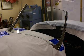
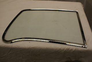
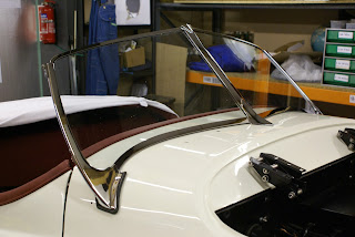
The long standing appointment with trimmer John Richardson looms ever closer, with friend Geoff's trailer booked for Monday 4th March to take the car to Shildon.  Two major jobs need to be completed in the next few days, neither of which I had really planned to do at this stage.  John tells me that he needs to be able to drive the car in and out of his workshop so it needs to be operational - just.  It also dawned on me the other day, that in order to make and fit the hood (soft top), the windscreen would have to be in place - duh!
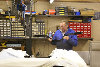
So with two weeks to go, the snoozing and socialising will have to stop.  John has already completed the dash board, seats, armrest and door panels and I would have to say that he has made a superb job of them.  The remaining work, hood, tonneau cover, cockpit rolls, side screens and carpets will be tailored specifically to the car, hence the need for it to be away at his workshop for the best part of a month.


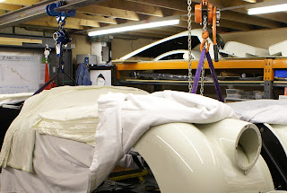
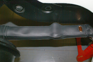
Special dispensation given to store seats at home for a while

Exceptional job by John Richardson of Shildon County Durham
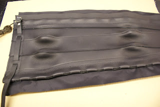
The seats in particular have worked out very well.  The bases are close to original but the backs have been changed from the slide around variety  to bucket.  This also allows for the central armrest to have an opening top with storage inside - something in very short supply in a 120 OTS.
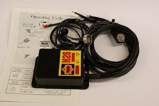
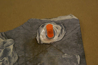
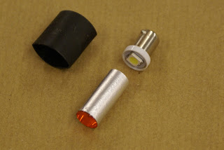
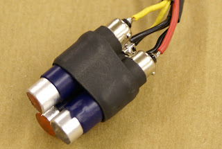
This is an ideal place to hide the controls for the ICE kit and other occasional use switches, plus a switch to activate a small digital display showing battery voltage, to avoid fitting a voltmeter, much more use than an ammeter if the cars been fitted with an alternator.
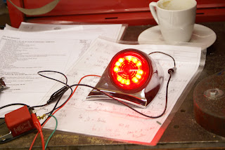
I had some nice period switch labels engraved but couldn't resist having a second set made up for the benefit of the grand kids.  Telling grandson Freddy that he shouldn't on any account open the lid between the seats in Bobsy's 'special car' then leaving him to play should be interesting, especially when the 'countdown' LED's illuminate immediately after he's activated the eject switch.
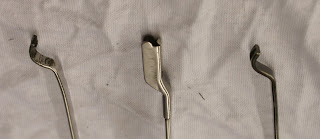
Work in progress with alternative label for grand kids
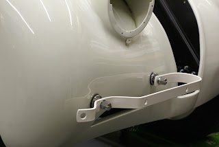
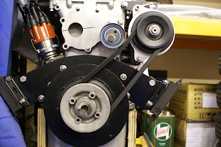
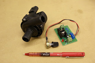
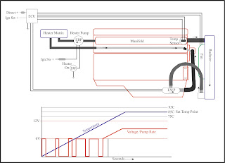
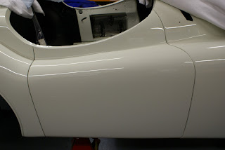
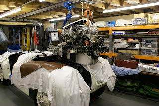
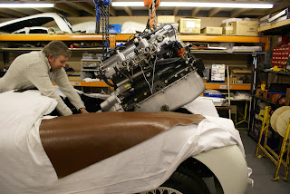
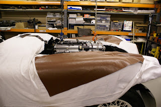
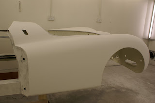
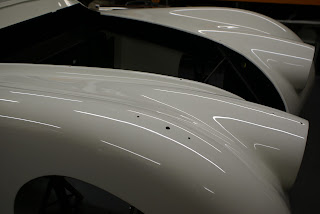
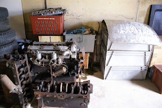
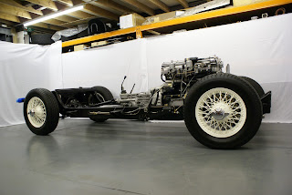
 With the engine installation imminent, the past week has been spent fitting out the engine bay and completing any other jobs which would be harder to do with the engine in place.  The plan is to fit the engine on Sunday 17th Feb and hopefully most of the ancillary bits, exhaust system etc.  A few years back, young friend Kev Woods gave me hand to remove and re-fit the engine in my 140 when it developed an oil leak and will be on hand again to assist which will make the job a great deal easier.  Kev's day job involves maintaining heavy plant and machinery, often on site, so for him, this task should be fairly straightforward and his help invaluable.
 
Engine bay - almost ready for engine installation on 17th Feb
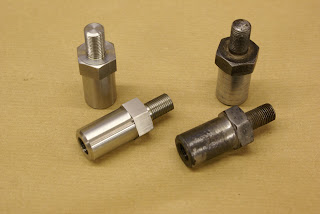
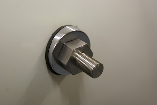
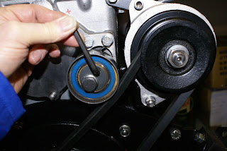
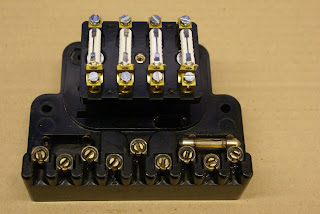
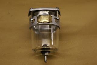
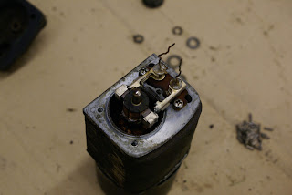
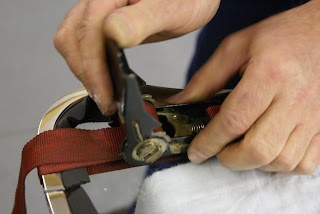
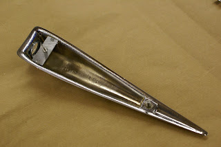
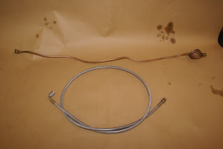
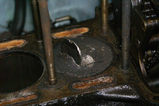
One item I wasn't too happy about re-using was the brake fluid reservoir - made from glass !!
Thinking about this, I realise that the early 120 master cylinder (also used on the 140) effectively has its own reservoir holding around half a pint of fluid which in turn is kept topped up by the glass one.  I can only guess that the glass reservoir was added to make it easy to check the fluid level and top it up.  In any event, it was a very satisfying part to recondition.  New rubber seals were made and fitted top and bottom and the metalwork powder coated in a colour very close to the original.  Local and ever helpful company Hawk fasteners actually had in stock the tiny rivets used to fasten the brass manufacturers plate back in place.
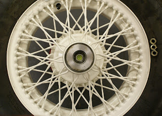
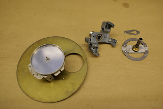
Master cylinder with its own half pint reservoir - ready for assembly


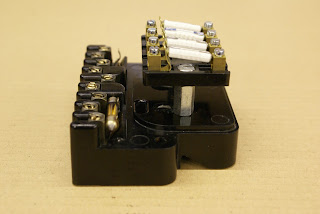
Glass brake fluid reservoir - scarey!
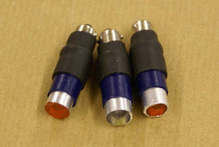
Lovely original brass plaque
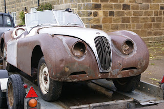
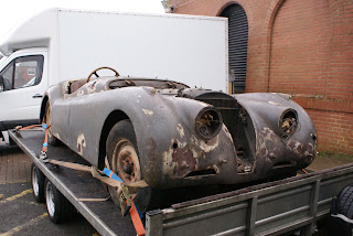
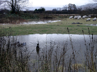
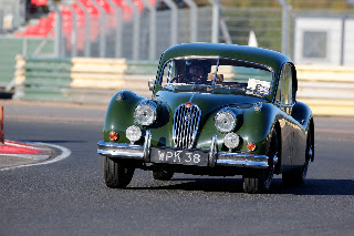
Miscellany

The weather today, Saturday 16th, has taken a turn for the better, so time to disinter the 140 from it's winter slumbers.  I've run the engine and moved the car a few feet back and forth every couple of weeks, but this will be it's first run out this year.  As ever it started without any fuss and ran beautifully with all gauges indicating healthy levels of everything.
Just around the corner from my workshop is a newly re-furbished building dating from 1916.  Originally the HQ for the Cargo Fleet Iron Company which peaked in output in the 1950's and may even have made the steel used in the 140's construction.  The entrance makes an interesting backdrop for a photograph. 
Preceding this building by around fifty years, Prime Minister William Gladstone, visiting Middlesbrough's Iron Foundries in the 1860's described the town thus :
"This remarkable place, the youngest child of England's enterprise, is an infant, but if an infant, an infant Hercules"
I can't help but wonder what he would say if he could see the town in middle age.
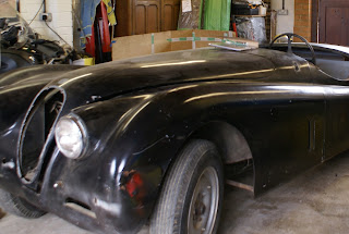
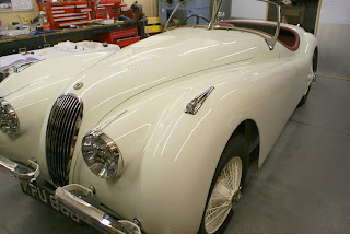
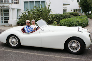
140 after its winter break, a little dusty but otherwise superb
 Now here's an extraordinary thing.  Last year I insured my ancientAudi S4 Avant with Saga and literally halved the premium from the previous company.  (never thought I'd see Saga and S4 in the same sentence).  My Renewal Schedule arrived the other day and around the same time an invitation to renew my AA subscription.  An all singing and dancing Gold family membership, this had previously been paid by the company by recurring Direct Debit so the gradually increasing cost, this time £202.96 had not been flagged up.
Now retired with the company DD cancelled, it would from hereon be up to me. So, I had two calls to make, Saga and the AA.  Fortuitously I chose Saga first.
Answered by a UK call center, no multiple choice button punching, recorded messages and music, just a charming young man called Zack, who efficiently arranged my renewal.  He went on to pitch for breakdown cover, in conjunction with - you've guessed - the AA.  I read from my renewal document exactly what £202.96 provided and explained that was precisely what he needed to quote for, stressing each aspect, family membership etc. He absolutely confirmed it would be identical, and quoted me £37.00 yes - thirty seven pounds!  I look forward to receiving the documents to see if this can be true.

Next Post end of February

POST 50 - MARCH 2013 - ANOTHER MILESTONE

$
0
0
Finally got round to bringing this blog up to date, around a week late.
Its quite a coincidence that the fiftieth post should also record a bit of a landmark event, the car more or less in one piece being driven out of the workshop and onto a trailer for its trip to the trimmers at Shildon, about 25 miles away.  Never the less its been quite a hectic couple of weeks and things have been far from straight forward.  Making the car drivable took a week or so out of the time I'd allowed to prep it for trimming, so a little help was organised for a couple of days in order to achieve the deadline.  Trimmer John is a busy lad with a queue of work lined up and if I'd missed my slot, it would have made a mess of both our schedules, hence the need to get it there on time.


The biggest single problem was the attempted fitting of the windscreen pillars (which would allow the hood to be made and fitted). The original pillars were missing but I had acquired a set of three new ones and foolishly imagined it would simply be necessary to bolt them in place.  The side pillars are bolted through the bulkhead into threaded plates, again missing, so I made these up from heavy bar, and with great difficulty and much cussing fiddled them into place using a pull cord. After endless hassle I eventually had the side pillars bolted in place and offered up the windscreen glass to check for fit.

Trial fit of screen glass (without chrome surround)
 The passenger side was not too bad, but the drivers side was way out.  This initially looked like a major disaster until I realised that relatively small tweaks of the fixing points moved the pillar significantly in whichever direction required. The rearward slope for example could be easily changed by several degrees which probably accounts for the badly fitting side screens and loose hoods I've seen on several other XK's.
I do have the original side screens which are due to be re made at the trimmers, and will ultimately dictate the correct angle for the pillars, along with the glass and hood front frame, which will then dictate final position.  The upshot of this is that the hood will have to be tailor made later once the doors and sides screens are in place.
I can remember a similar problem with my Daimler Dart (SP250).   I eventually got around to fitting the hood just before I sold it.  In the preceding twenty odd years of ownership, I often used it as a daily driver which meant that my kids eight mile trip to school was spent scrunched up under the tonneau cover when it rained.

Fitting the engine back in went very smoothly and exactly as planned but did involve two hoists and three men.


The pictures above give a general idea of the sequence.  Using a pair of hoists gives very precise and easy control of the angles required to install the engine with the gearbox attached.  It was also necessary to temporarily remove the round tie bar that normally sits just in front of the radiator.

The conversion to a five speed gearbox meant that the gearbox cover would require some modification to accommodate it's slightly different dimensions.  Fortunately the gear stick is in exactly the same place so nothing too major.  Playing around with cardboard, I worked out the general shape of the extra bit, then cut this out of sheet aluminum. 

Gearbox cover mod ready for folding
Check for fit

Pop riveted in place and 'Dynamated'
Folded and pop riveted to the original, then covered with Dynamat, it's slightly different shape when fitted with a leather gaiter and carpeted and  should be hardly noticeable.

Floor and boot boards were cut out from 12mm Marine Ply, given three coats of exterior black varnish on the underside, then stained and wax polished on the top side.

The original heat shields between the silencer and floor boards were made from asbestos and one of them was missing.  As an alternative I used Duratec 750 Insulation Board which is a 6mm thick asbestos free calcium silicate plate. (RS Components Stock No 248-4630)  Expensive but very high spec, which it needs to be given that the silencer is around two inches (50mm) below the marine ply floor boards.

Aluminium extrusion with Rivnuts inserted to hold heat shield
Heat shield in place - sits about an inch above silencer!
So, with numerous other small jobs completed, oil, water and petrol were added.  The ignition and choke wiring was jury rigged and the flannelette sheets stripped off.  Then finally and unceremoniously, it was started and for the first time in fifty years moved backwards and forwards a few inches under it's own power.


Just needs doors fitting

Monday March 4th - Doors were fitted and it was driven out of the workshop and and a few hundred yards up and down the industrial estate road, but with great care as only the hand brake was functional.  Geoff arrived bang on 10.30am and it was ensconced safely in John's workshop at Shildon by 11.30.

JPEG from Geoff so small image
Next Post - Mid March  (won't be late!)

POST 51 - MARCH 2013 - SCREEN WIPERS

$
0
0
Although my official retirement date was the end of December last year, the reality of retirement is only just starting to kick in.  I continued to help out during the transition up to the end of February but the normal pressures of business are now totally gone - forever, so it's strange to wake with the thought - what shall I do today?  This is even more the case with the car away at the trimmers

First job in the workshop is to take advantage of the space and have a sort out of parts.  A few small items have been mislaid over the past couple of months, but will hopefully appear in the process of reorganising
things.
Long overdue sort out of remaining parts

Since the beginning of this year I've deliberately avoided doing anything that can be done whilst the car is away at the trimmers, so that I would not be 'kicking my heels' for a month or so.  Consequently I have a small list of jobs lined up for the next few week, the first one being to strip and re-con the wiper motor and rack, or possibly upgrade it.


Before starting on this I did some research and looked at alternatives.  The original item has a few downsides in that it is single speed, not self parking and uses a wound field coil motor rather than the later and more powerful / efficient permanent magnet type. Will it still work after around sixty years of inaction, and if so, could it be made to operate satisfactorily in spite of its drawbacks?  With the rack removed I applied 12 volts with a 2 amp limit to avoid any disasters but nothing happened.

Grease is solid due to fifty years of inactivity - no wonder it wont run.

Looking at the almost solid grease in the gearbox this wasn't really surprising so the gearbox was also removed, but to no avail.  Next the end cover was removed then the brushes.  It was clear now that the output shaft was seized solid in its bearing, probably just through lack of use.

Output shaft (other end) seized solid in it's bearing

I left it to soak in a shallow bowl of thinners then turned my attention to the seriously 'gunged' up gearbox.  This was stripped, cleaned and checked for wear.  Once cleaned up, every part looked almost as good as new (as did the motor commutator and brushes).  I was quite impressed by the design detail of the gearbox, particularly the two sets of needle roller bearings supporting the intermediate gear driven by the motors worm gear.

Nicely made with two sets of 15 needle roller bearings to support intermediate gear
 
After an hour or so of soaking, the rotor shaft was free allowing the rotor to be withdrawn.  After a good clean and a coat of crackle finish paint to the motor casing, it was re-assembled and again connected to a 12 Volt supply.  This time it ran beautifully drawing just over 2 Amps without any load.  Increasing the load by slowing the worm gear drive increased the current draw by up to half an amp.  This will be a very useful way to determine the friction created by the gearbox and rack.

Motor cleaned, painted and re-assembled - as good as new

Next the gearbox was added and the current draw remained constant indicating that all was nice and free with little friction.

Gearbox added - no increase in friction


The motor with gearbox attached was left running whilst the rack and wheel boxes were stripped, cleaned and given an ample coating of Graphogen grease.  Again the wheel boxes were in exceptional, good as new condition with no perceptible wear.
The whole assembly, motor, rack and wheel boxes were now reunited.  Initially the current draw was around 0.3 Amps higher but slackening the rack retainers on the wheel boxes brought it back to around 2 Amps.  Playing with the positions of the rack outer casing ends and gradually tightening them up with the motor running seemed to allow them to settle into their preferred location and the 2 amp draw was again achieved.  After a couple of hours running, the current actually settled to 1.7 Amps (20 watts) which I would guess is about right.

Rack and wheel boxes added.  Current settles to 1.7 Amps when run in.

There seems to be an abundance of torque available at the spindles, (I can't grip them well enough to slow them down) and I can't help wondering if the bad rep the original set up suffered from was partly down to poor assembly and lubrication, generating high levels of friction.

The dash board now has the benefit of connectors so is much easier to remove which makes access to the wiper assembly straight forward.  If it transpires that they are in fact hopeless then I will have to look at upgrading.  Local fellow 120 owner Tony Hamnet wrote an excellent article in the January 2013 XK Gazette detailing everything necessary to fit a more powerful two speed, self parking arrangement.  Quite an involved bit of work not to be undertaken lightly but good to know it can be done if necessary.

Uniquely for an old car, my XK140 fixed head has excellent self parking two speed wipers, but I really miss the single wipe facility of a modern car.  In the UK it's as likely to 'drizzle' as it is to rain making a single wipe facility much more useful than a second higher speed.  So one possible side benefit of the original very basic system is that it may be possible to add a second switched supply to the motor via some sort of pulse switched timer relay allowing for a single wipe. With a mere 1.5 secs for a wipe back and forth, getting the timing right might be a problem or even impossible but it could be an interesting and cheap solution.  I'll look into it.  In the meantime it'll be fun honing the skill of switching off at exactly the right moment to neatly park the blades in the right place.

Miscellany
Trimmer John was most adamant about the need to be able to drive the car in and out of his workshop, so the run up to its delivery to him, due to this additional work, was very busy.  I had not intended to install the engine until April and bringing this forward meant not doing a few other jobs.  Consequently I was duly chastised for my lack of preparation.  As the starting procedure was complicated by the battery isolator switch and immobiliser I had written out the order of actions - Isolator on - blip immobiliser - ignition on - choke on if cold - starter button - then - choke off after a couple of minutes.   I explained all of this to John and his response was "all looks a bit complicated - I don't think I'll be bothering to move it after all".
Good trimmers are hard to find so I bit my tongue!

Next post beginning of April


POST 52 - APRIL 2013 - ENGINE COSTS & SCREENS

$
0
0


I’ve been putting this off for at least a year but knew that sooner or later I would need to commit my invoices (which I leave in various places but rarely lose) onto a spread sheet.  With the car being at the trimmers and not much to do in its absence, coupled with outside temperatures rarely exceeding zero degrees it seemed to be the ideal time to stay at home in front of the fire and PC and punch in the numbers.   I had a pretty good idea of what I’d spent so far, but it still came as a bit of a shock to see it on the page. 

Car away at trimmers so empty workshop - all set for the final phase
 XK prices in general have been doing quite nicely recently so this is not too much of a worry, good fortune, rather than good management on my part.  I've had a very enjoyable hobby for a couple of years and depending on a realistic valuation on completion, probably at little cost.
 
I am however, very much aware that by mid June I will have spent something approaching 2,000 hours of what would have been‘chargeable time’ if I had simply given the job to one of the several specialists in the area.  I must have also spent maybe another 1,000 hours generally (but enjoyably) pratting around.  Even allowing for the seriously better work rate of a restoration pro, I reckon I would have been billed for 1500 hours at say £35.00 an hour making a VAT inclusive additional cost of £63,000 !  I guess it just depends on which way you want to look at it. 

Once the invoices were committed to a spread sheet, it was a relatively easy step to allocate nominal codes to each area of the work, then sort the columns to give a breakdown of costs.  The most interesting result, I think relates to the engine rebuild.

Comprehensive cylinder head re-condition £1,730.33 inc VAT
 
Block re-condition £3,321.88   Grand Total £5052.20 inc VAT


Back in July 2009 VSE re-built my 140 engine at a VAT inclusive cost of £3,800 including a rear oil seal conversion.  I did have the additional cost of delivering and collecting to mid Wales, (twice as it turned out due to an oil leak - "pop it back and we'll take a look"), a round trip of some 450 miles.

My VAT inclusive cost for the 120 engine is just over £5,000 - doing almost all but the machining work myself.  Allowing for inflation and travelling costs, not too different to the VSE job.  I suppose the benefit is that I know exactly what has gone into the 120 engine and I have taken great care at every stage of re-assembly.  It also benefited from some superb quality forged pistons, valves, guides and rear oil seal from Dan Mooney at Classic Jaguar in Austin Texas.
For anyone considering a DIY engine build, the above costs make for interesting reading.  If your doing it for satisfaction and a sense of achievement, fine.  If your doing it to save a few quid, forget it!
Thank heavens, it seemed to run superbly in the three hours of effective bench testing (in the chassis) but I won't feel totally confident until I've got a couple of thousand miles on the clock.  I think I used this picture in a previous post, but it's such a lovely thing, it deserves a second look.


Hope it goes as well as it looks.
 The car came back from the trimmers exactly on schedule on March 21st and it all looks pretty good. The first job to complete is the assembly of the side-screens.  These can then be fitted to the doors and this in turn will allow me to get the angles of the windscreen pillars exactly right.  Trimmer John has not finished the front edges to allow a little lee way between them and the pillars.


Initial trial fit of side screens - New trim now in place

Assembling the side screens was challenging.  The frames and perspex edging were all original, just re-chromed or powder coated, so they should have gone back together easily. An estimated couple of hours turned into a good days work but they did look pretty good once finished.
 
With perspex and chrome trim in place
 Next up was fitting the chrome edging to the windscreen.  The screen glass is quarter inch (6.3mm) and the channel is between 8.2 and 8.5mm wide so I ordered some 1mm rubber strip from Woolies.  Even with lots of lubrication, it was clear that it didn't want to go together and something was going to get bent or broken.  Checking the strip thickness it turned out to be 1.2mm as did another 1mm x 25mm x 5Mtr roll from COH Baines.  You wouldn't think 0.2mm would make much difference, but try as I may it refused to cooperate.

An alternative solution was required.  My 140 Fixed Head Windscreen was expertly installed by Paul from Windscreens Northern, an independent fitter who specialises in Sports / Classics.  After an initial look at the problem, he arrived a few days later with the correct sealing material and with the assistance of some ratchet straps soon had the problem licked.  There are some jobs best left to the experts (if you can find one).  Fortunately I surrendered before the inevitable disaster occurred.

Component parts ready for assembly

Closed cell foam unlike rubber will compress and cushion
Ratchet strap solution to gently pull it all together

All done, with thin bead of sealant to finish off
I now have absolutely no excuse for not fitting the windscreen pillars and carefully aligning them to accommodate the side-screens and hood frame and I just know it's going to be a horrible and exasperating sort of job. I wonder how it would look with aero screens instead?

Next post mid April

POST 53 - APRIL 2013 - SACKED (AGAIN) & STEERING WHEELS

$
0
0
From the moment the car came back from the body shop, it's been swathed in sheets.  So many, that the lady in our local general store must think I have some weird thing about flannelette, or maybe am incontinent and have a broken washing machine.  Never the less it's been worth the effort.  In the best part of six months, it has suffered not a single mark, scratch, or chip of any sort until .............

After a considerable fight with the windscreen and it's various component parts, I finally got it to fit really well.  All that remained was to re-fit the two pairs of large bolts / nuts that hold the bottom part of the windscreen side pillars to the bulkhead.

Windscreen finally in place and looking good
On the last of many trial fits, I'd worked out how to get washers and nuts onto the ends of these bolts in an extremely confined space by sticking them onto a finger with thick cavity wax and working my hand up inside the bulkhead.
With three down and one to go, I'd really got the hang of this quite difficult process.  The final washer was slipped over the end of the fourth bolt and then I managed to turn the bolt into the nut by a single thread.  It's not easy to explain this, and I can only guess at whats going on in this dark recess as its impossible to see into, but the nut must have gone on cross threaded.  Unaware of this, using a half inch ratchet I then wound the bolt in, through the pillar and bulkhead panel.  I met a little resistance at first and then it went tight sooner than expected.  Something was clearly amiss.  I realised what had happened even before looking around the windscreen to see the result.

If I was employed by me, (or Alex) I would have been sacked for this.
The nut had been effectively pushed into the underside of the body, distorting it and cracking the paint.  Now I have to face Alex at Auto Bodycraft and explain how I managed to ruin his beautiful paint job.  I will no doubt get a well deserved bollocking for being careless, and quite right too.  Just how he sorts this will be interesting, challenging and most likely expensive. 

The short term outcome was that I was left in no doubt that had I been in his employ, my trial period would have ended abruptly.

Talking of Alex, I mentioned in passing that I was about to send my steering wheel to Myrtle Productions in Kent to be re-furbished.   Some years ago, they did a superb job on my 140's steering wheel but at £340.00 so they should have.
 
120 Steering Wheel - Picture taken two years ago - April 2011

The 120 wheel looks virtually identical to the 140's but is of an entirely different construction, actually making it a little easier to restore to its original finish.  The rim and boss appear to be castings of some type of non ferrous / non magnetic material, but the rim in particular seems heavier than aluminium.  The spokes are steel, so how they are attached to the boss and rim is a puzzle.  The 140 rim by contrast looks like resin laminated onto a steel former.  It eventually de-laminates and I guess it's refurbished in some sort of mould.

The finish on both wheels appears identical and very specific.  Not quite gloss, but a little more shiny than satin black with a very deep sheen, similar to a glass fibre gel coat.  Alex felt sure, he could achieve this, so I left it with him on the basis that the 140 wheel would be the only acceptable (read chargeable) standard. 


Start of prep on 120 steering wheel
First off Alex ground out the cracks, then filled them with Q Bond adhesive / filler followed by an unlikely named product called 'Upol Fantastic Filler'  This was followed by three coats of 2K primer with lots of rubbing down between, then finally five coats of Mipa 2K Acrylic Super Black. Time consuming and not cheap, but still quite a bit less than Myrtle would have charged, plus the finished article was certainly equal to, if not better than the 140 wheel.

Ready for a final polish

And finished product - Refurbished steering wheel looks superb

140 FHC - interior starting to look a little worn but is very well used


Miscellany
My Great Grandfather, George, was born at Tanton Hall (two miles from my home) in 1869, to a housemaid, Annie Elizabeth Hugill.  She was listed on his birth certificate as a 'Spinster of this Parrish'.  In the box for father, it simply said 'unknown'.  George was adopted in 1870 by a local Publican called William Exelby.  His second son, my Grandfather, was one of four brothers, all born between 1894 and 1897.  From that point, the male offspring expanded rapidly over the next generation, but then through various mishaps, war and an unusual profusion of daughters, the male side of the line gradually diminished.  With a relatively unusual surname, (the last time I checked in the London Phone book, not one Exelby was listed) it didn’t take a great deal of effort to establish exactly how many male cousins, half and quarter cousins were still around and if they in turn had any male offspring.  The surprising answer was none.  I have a daughter and son, so the continuation of the male line and family name rests squarely on my son Danny’s shouldersand of course his wife Laura.  So what's the relevance of this preamble?

Dylan Robert Exelby - Born 7th April 2013
Strange to think that Dylan Robert could feasibly see the family name into the twenty second century.  I can't help but wonder what on earth he would make of this blog if he read for the first time when he is say 80.  Conversely, not even Jules Verne, if he were still around, could I think come close to predicting what life will be like in say 2093.
To give this even more context, going back rather than forward 80 years, below is the last page of a letter from my father, post marked 1935, to his mother.
Aged just fourteen, and with a shilling (5p) in his pocket he was sent to work at a farm at Barnard Castle, some forty miles away.  Written a few days after his arrival, he asks for some more 'cash'.
Having spent his shilling and accounted for it, he nicely emphasises how broke he is with his post script - "I have no ink so I have used pencil" 


Next Post early May


POST 54 - MAY 2013 - LED SIDE LIGHTS, INDICATORS & BRAKE LIGHTS

$
0
0
At the beginning of February I spent some time looking at incorporating LED indicators into the front and rear side lights. Realising I would be pressed for time to meet the agreed date to send the car to the trimmers, I put this on the back burner after finalising the design for the rear lights and making a prototype which seemed to work pretty well. -  (Post 48)
The available space within the front side light was very limited and a solution using individual LED's (based around the rear light design) proved unsatisfactory.  To resolve the space issue, I carefully removed the lamp holder from the lens assembly.  This effectively gave me an empty side light housing to play with.


So, time for a re-think.  Fortuitously, friend Nick dropped in to use the facilities to fettle an amateur radio aerial, and we got chatting about the indicator project.  Nick has an amazing knowledge of all things technical and electrical in particular.  Consequently, pre-wikipedia, "Nick-L-Know" was the standard response to most technical queries. 


Nick Peckett   AKA Peckett of Kabul

Nick has spent the final third of his working life developing the mobile phone network in Afghanistan, his company initially working for the Taliban, then after 9/11 for the first commercial Afghan Celular /Internet operator.  This unusual and rather dangerous occupation took him all over Afghanistan but as the local populous, regardless of allegiance quite liked the idea of making phone calls, he was generally welcomed in even the most hostile of places.  So what did 'Peckett of Kabul' suggest :

"Why not just take a conventional forward facing super bright LED bulb, stick it to a short length of orange plastic tube and wrap the tube in silver foil to stop the light escaping.  This can sit inside the side light housing along with another LED / clear plastic tube for the sidelight".  Simple.

11mm OD plastic tubes bought from ebay

The initial result was not encouraging with the tube seeming to attenuate the light significantly.  Polishing the ends (as we do with fibre optic cables for RF transmissions)  completely resolved this allowing the full intensity of the bulb to shine through.
 
ends polished up on fine emery paper and chrome polish

Pre-assembly

A few turns of insulation tape (blue in the photo) nicely brings the OD of the tube up to that of the LED.  The LED is then joined up to the tube using a short length of heat shrink. As the indicator need to be brighter than the sidelight, I doubled up on the orange.

two orange indicator lights should differentiate them from single side light

They are wrapped together to form a triangular shaped package which fits snugly into the sidelight pod.  If I need to access them in future it will involve removing the light from the wing but assuming the LED's live up to their specified life of 50,000 hours, this really isn't going to be an issue.
 Not having B9AS lamp holders to hand, I soldered tails directly onto the bulbs.  This is quite a tricky operation, requiring just enough heat to flow the solder without melting whatever else is connected on the inside.
Albeit some time ago, years of fault finding down to component level, removing and replacing integrated circuits with tiny soldering Irons lets me get away with this, but it's very easy to get wrong and with the LED bulbs currently costing over a fiver, not really recommended.


Lash up to prove the principle - fits neatly into light pod

The tails are wrapped to form a three wire loom which goes through a sealing grommet in the wing and is terminated directly into the IP66 junction box. (First picture on Post 47)
This is all very much a 'lash up' to prove the principle and subject to it performing as required will be developed into a rather more professional looking package.


Side light - very bright even in fluorescent light / daylight


Indicator in twilight - surely unmissable


Flushed with success, I now turn my attention to the brake lights.  I've never liked the idea of them sharing a bulb with the sidelight.  During my 140 restoration I added a set of red LED's to the number plate / reverse light to provide an additional and separate brake light.  I still had some red LED's left over and it was relatively easy to make up a similar arrangement setting them in a large grommet which simply sits around the reverse light bulb.  To complete the set up I replaced the remaining bulbs with LED's


Brake light added to the reverse / number plate light - all LED's


Just the job

Miscellany
On my 'to do' list for a few years now has been the design and manufacture of a camping type chair that doesn't take up a chunk of space in an XK's limited boot / trunk.
Every once in a while, I've searched ebay for just such an item, half hoping that someone had invented it already to save me the trouble and half hoping they hadn't.  In reality, an ambition too far that I was content to live with rather than do something about.
With the rally season about to start and my existing space consuming camping chairs on their last legs so to speak, I had another look and their it was.  Made by Australian company Helinox, it weighs 836 grams and more importantly folds up into something approaching the size of a shoe box.  I bought a couple of them and they are quick and easy to assemble and very comfortable if a little wobbly.  With a capacity of 145Kg, even my portly frame only takes up 65% of the design max so it should be OK.


Helinox Chair 1 


Next post mid May


POST 55 - MAY 2013 INDICATOR SOLUTION & NUMBER PLATES

$
0
0
Front Sidelights / Indicators
Whilst the front sidelight / indicator combination worked in principle, it did need to be tidied up.  First off I found some BA9 lamp holders and then some very high power 1W amber BA9 base, LED's on ebay from  http://stores.ebay.co.uk/Wholesale-Xenon-Lights-Store in the USA at about £3.00 each. A short length of 1.125 inch hexagonal bar (again from ebay) had a pair of 1/4 inch slices cut off it.

Basic components for one side.  Note tiny PhotoMOS Relay

Three 10mm holes are then drilled to accommodate the lamp holders.  These are a nice interference fit and a little superglue dribbled around the sides permanently fixes them in place.

Hex bar drilled to accept 10mm OD BA9 lamp holders

Because the sidelight Cree type LED is so immensely bright, the indicator amber LEDs are nowhere near as crisp and distinct as when the side lights are off .  This is especially noticeable when viewed head on due to the narrow angles of illumination. So whats required is for the sidelight to temporarily extinguish exactly as the indicator comes on, a job for a normally closed relay.  Because the LED's draw such a small current (20mA) we can go one better and use a solid sate Photo-MOS type relay, small, very fast switching and hugely reliable. 


For those unfamiliar with the operation of such things, here's how it works :
With the sidelights on, the 12V supply is connected to pin 4 and as the relay is normally closed, the supply continues to pin 3, illuminating the white sidelight LED.  When 12 volts appears from the flasher unit, as well as going to, and illuminating the two amber LED's, it also goes through the 470 Ohm resistor to pin 1.  This triggers the relay to change state to open circuit between pins 3 and 4 turning the sidelight off.  If you want the sidelight to temporarily dim, then connecting a 1KOhm resistor across pins 3 and 4 will allow limited current flow.

Again, note tiny relay with pin 2 soldered onto common earth

Heat shrink tidies it all up and prevents accidents

If your 120 has the later sidelight arrangement where its not a separate item, I believe the aperture for the front lens is considerably wider at around 1 and 5/8 inches (the chrome item above is less than 1 inch) so the assembly should just fit nicely straight through the front, once the original lamp holder is removed.

I would have to say that the finished product worked superbly.  The change to brilliant orange is so fast that your not aware the the sidelight has been extinguished and there is no way that anyone could mistake your intentions.  Fitting the 1K resistor would technically leave the side light on but I think its better without it.

Sidelight around three times brighter than original filament lamp
Photo makes indicator look yellow when its actually very bright orange / amber
The final part of the indicator upgrade is the fitting of a cheap but loud 90dB Piezo sounder.  With non self cancelling indicators this is a pretty essential item and guarantees that you'll never leave your indicators on by mistake.  Total cost for the front sidelight / indicator components - circa £40

Number Plates
The general consensus seems to be that the original number plates were most likely but not necessarily made by Ace.  Looking closely at the picture of my car when two weeks old, they do seem to look like Ace type cast aluminium numbers.  These are still available from Framptons and I opt to buy the individual numbers in order to make up my own plates, thus getting the plate dimensions exactly right.  This also saves me £80, but they are nevertheless expensive at £16.25 per number. 


Easy solution to get the pin holes in exactly the right place
The numbers are arranged on a sheet of cardboard, the pressed down to leave a mark where the fixing pins go.  The cardboard was then stuck to a sheet of 2mm aluminium and the marks centre-popped. 


Plate ready for powder coating satin black
The Aluminium plate was then drilled to accept the number pins and the reverse side countersunk. The plates were sent off for powder coating satin black.  Rather than use the cir-clips provided, I reduced the pin lengths to 2.0mm, pressed the numbers in, then epoxyed the pins into the countersunk holes.  This made the backs of the plates flush allowing them to be fastened flat to the number plate pressing.  I also sealed the plate to the pressing with a thin rubber strip to prevent water ingress between the two.

Numbers should possibly be little less shiny - time will sort

Front end almost finished


Miscellany
Two events since my last post.  The first being a track day at Croft racing circuit.  Feeling guilty about neglecting my frog-eye sprite, I spent some time giving it a general service and sort out and on the day it repaid me in spades having no trouble seeing off several TR's and even a modern MGF.  (See post 21 - January 2012 to find out how this could be).  Great weather for a change and a truly brilliant day which everyone enjoyed, even Nick who was black flagged on every session in his new Audi RS3.  Your 66 Nick, (or is it 67) and I really think its about time you started to take some responsibility for your actions.

Frog-eye punching well above it's weight

Porsche 911 - probably slip-streaming to gain an advantage
 Stratstones, the local Jag dealers made an appearance with a new F type during the lunchtime break and as we had a couple of C types, a D type and a few E types already present, it was a great photo opportunity.  The best shot I got was of them coming out of the hairpin onto the pit straight about 150 yards distant. Great composition but crap quality.

CDEF - Possibly a photographic first?

The second event turned out rather less memorable.
I volunteered to spend the day marshaling for the Jaguar Drivers Club annual rally last Saturday.  This event had previously been organised and run by the same man for quite a number of years and I suspect that for some regular entrants, this was the extent of their world as far as rallying goes.  For whatever reason, possibly because it was held in the North East, a new organiser was brought in.  His brief was to put together a navigation / regularity event based on MSA regulations and licences and that is precisely what he did.  Unfortunately, the gap between the expected event and previous experience of the competitors and the delivered event strictly in line with MSA regs was rather large.  The new organisers not unreasonably assumed that the competitors were all seasoned and consummate enthusiasts whereas at least half were simply out for a pleasant Saturday afternoon sociable drive through Wensleydale.  The best that can be said is that both organisers and competitors were equally unimpressed with each other.
The day was not helped by wind and rain spoiling the magnificent views on route.  Additionally, the lunch stop at a Wensleydale Hotel further wound up the already exasperated  assembly by charging a tenner a head for a mediocre bowl of soup and a Sandwich.  By the time we got in from the rain after arranging the parking of the 45 cars, the soup was barely warm and the sandwiches had all been eaten. Worst of all, I had left my carefully prepared Mrs E's finest home made soup and ham sandwiches behind after the promise of a good buffet lunch at said eatery. 


POST 56 - JUNE 2013

$
0
0
 It must be almost a year or so since I almost completed the braking system, when due to a series of not quite correct parts being supplied with the front disc brake conversion kit, I became so frustrated with it that I abandoned it and moved on to other things.  Very conscious that sooner or later I would have to sort it, I dug out the various pipes, converters, brackets and unions that had caused me so much hassle. Clearly in the intervening year, the supplier must have driven north, broken into my workshop and swapped the offending parts for the correct ones because after a bit more head scratching I managed to more or less figure out the assembly sequence of the pipework from the chassis lug to the calliper.


Flexible pipe from chassis lug to bracket - Just look at that dust!

And solid pipe - bracket to calliper.   Really should paint shocker black
 I also swapped out the nyloc nuts initially used to fasten the discs to the hubs, for the all metal lock nuts eventually supplied with the kit.  With the system now fully assembled, I went around every union and checked for tightness before filling with brake fluid.

Brake Fluid - now there's a subject guaranteed to to start a fight at an otherwise polite meeting of mild mannered Jaguar Drivers Club members.  Silicone, Glycol, DOT 3, 4, 5, 5.1 Soft pedals, swollen seals, damaged paint work, the list of complaints and opinions goes on and on.  Having used both types over the years, with and without problems, I considered it worth the effort to spend some time researching this and eventually found what I consider to be the definitive article on the subject.
http://www.mossmotors.com/forum/forums/26292/ShowThread.aspx 
To summarise, it seems that Silicone is best in classics, especially if its an all new / re-built system with no Glycol residue to mix with.  An additional benefit and very important to me is silicone's inability to ruin a nice paint job.  So Silicone it is.

With half a litre of fluid in the glass reservoir I started by bleeding the front off side simply because I could pump the brake pedal lever by hand.  A few gentle strokes and  a minute or so later I had puddles of various sizes under almost every union.  It took a great deal of time and effort to sort this as I am wary of over tightening hydraulic fittings so just kept nipping them up a little at a time.  It would have been possible and so much easier to completely sort the breaking system at rolling chassis stage.


How on earth do you fit the Oil pressure / water temperature gauge.  I thought the 140 was difficult, but this is nigh on impossible.  The gauge must be fitted in the instrument panel and the solid oil pipe must be attached prior to attaching the instrument panel to the main dash board.  The arrangement is naff and does not lend itself to maintenance in the event of a future electrical problem behind the dash.  Also the water temperature pipe whilst thinner and more flexible is a permanent fixture to the gauge and it would take very little to damage it.  There are times when originality must be sacrificed, so Cleveland Flexible Engineering to the rescue again.  This is a fantastic operation more used to making up huge hydraulic pipes for heavy plant, but very happy and immensely helpful with smaller jobs. 

Flexible pipe to replace solid oil pressure gauge feed pipe.
Unfortunately it turned out to be a little more complicated.  I had checked the unions threads with a 3/8 UNF bolt which seemed fine. (same as the brake pipes)  On trying to attach the new pipe to the gauge it went tight after a few turns.  Checking out the male connectors on the filter and the gauge they are 3/8 but as near as I can ascertain SEI - 28 TPI (Standard English Invent-a-thread ???), not UNF 24TPI. Back to Cleveland Flexible who make up a couple of stub pipe converters.  This works out beautifully with the joint easily accessible from under the dashboard.

Stub pipe on oil pressure gauge - now accessible
Alex and Niel, the bodywork guys called in and gave me a hand to do an initial fit up of the boot lid and bonnet.  The plan is to actually drive the car to their workshop at the end of this week (6th June) where they will fine tune the fit of the hinged bits and also repair the damage I did when fitting the windscreen.  That leaves me a week to sort out a myriad of small jobs before its inaugural outing to my local Classic Car show at Stokesley on June 15th.  I then have just over two weeks to ensure it's fit enough to drive down to Poole on July 3rd to meet up with first it's first owner. 

Initial fit of bonnet - superb


Miscellany
I have two cars insured with Lancaster, my 140 and my Frog-eye sprite, both due for renewal at the beginning of June.  Lancaster are currently plugging Multi-Car policies for classics, so given that the 120 should be on the road in June, that looked like an ideal solution.  My Frog-eye cover is £121.25 and the 140 is £194.51 both including agreed valuations and the usual Legal Benefits scam at £25 a go with the classic get out clause "There must be a greater than 50% chance of recovering damages" - guess who decides that - certainly not me.  Anyway, I digress.
Reasonably assuming the 120 will be the same as the 140, insuring each car separately would give a total cost of say £440.  Quite a lot considering restricted mileages and the fact that I can only drive one at a time.  But this is where I'm bound to score with a Multi-Car policy with some handy discounts for the second and third cars.  Quotation - an embarrassing (for the poor sod who had to call me) £761.00.  But - as Jeremy Clarkson would say - it gets worse.
Obviously, the solution is to insure the 120 separately so I contact Lancaster again and ask them to quote for just that car.  No problem sir -  £960.67p.  Surely some mistake I say.  No sir that's the quote from our underwriters and is final.  OK I say, "I can insure one car for £960.67, two for £315.76 or three for £761.00.  He eventfully and very reluctantly agrees to go back to the underwriter and query it with a promise to call me back the following day.  I can honestly say that Lancaster have promised to call me back on at least six occasions and never ever have. A record that remains unblemished.
Checking with a few friends, Haggerty is recommended.  Literally fifteen minutes later I,m printing off the 120's Certificate of Insurance £276 lighter.  It could not have been easier, and the documentation produced could be a lesson in clarity to the industry.
Registration document and Insurance in hand and with no MOT or payment required, the local Post Office hands over the 120's first tax disc for forty eight years years.  Just need some brakes and lights now. (only joking)
 

The last time it was taxed was in December 1965 at a cost of Six Pounds Eight Shillings which I think would be for four months.

Almost 48 years since it's last tax disc.


POST 57 - JUNE 2013 - APPEARS TO BE FINISHED

$
0
0
When I started this project in April 2011, it seemed perfectly normal to spend some time estimating how long it would take and then to extrapolate a finish / completion date.  After all, that is exactly what I had done for numerous work related projects for the past twenty odd years.
Having fully retired at the end of January and with goodness knows how many potentially empty days ahead of me, it now seems like not such a good idea.  But I had made a point over the past couple of years that completion was scheduled for my 65th birthday on June 16th this year.  In addition to this, I now have a firm date of July 4th to get the car down to Poole in Dorset to meet up with it's first owner, Vernon Maitland.  This is such a incredibly rare opportunity that it must not be missed at any cost, so the last couple of weeks have been hectic.

Start and finish dates with schedule and reminders in between
The door gaps had been set up about a year ago, first with the body on a jig / frame then with it on the chassis on axle stands.  After a short run up and down the estate road it was clear that it had settled from those initial positions and the gaps had closed a little .  Putting it back on axle stands, each pair intentionally well in from the wheels, the door gaps were again correct, or even a little wider than required.

Door gap with chassis on axle stands well in from wheels

and with car back on it's wheels
I had already had the maiden voyage planned as a short trip of around ten miles to Autob-bodycraft to resolve the problem of the damage caused when I fitted the windscreen, so a re-shimming exercise was added to the list to correct the door gap issue.

The only other items to be sorted before the inaugural trip were the windscreen wipers and security bonnet catch.  I had pondered the possibility of a leather bonnet strap but was undecided about how they look.  One thing is certain though, with a strap over the front, there is absolutely no chance of the bonnet misbehaving so pragmatism wins out.  I order one from Guy Broads; its the type with two buckles which means that if you undo them both, you don't have the problem of the metal bits scratching the paint.  I'm also told that they are lined with soft Elk Skin which is less likely to scuff. Really?


With the central bit removed - no buckles to scratch paint
The car actually came with a pair of wiper arms and blades but the way the blades were attached to the arms was unusual and certainly not as original, but the arms looked to be of super quality and stainless so worth using if at all possible.  Fortunately I have an arm off my 140 as a pattern for the spoon bit that slips into the blade.  I manage to remove the strange clip affair which leaves a dimensionally correct straight end that just needs bending to the correct shape.  After heating to cherry red its bent round an old socket and after a bit of tapping about it looks pretty good and slips into the blade just as it should. 

140 arm end          120 pre mod              120 post mod
 After a few more very short runs I felt sufficiently confident to go for it, but only with my Audi following, full of tools and various get you home odds and ends.  I can remember every single first outing I've made with cars I've restored in the past and in particular driving a Morgan rolling chassis from Faceby to Stokesley (about 7 miles).  The seat was an orange box and it went and stopped but that was all.  To avoid capture by the local constabulary the journey was undertaken at round 6.00am in summer.  This felt very similar but it looked a good deal more legal.
Its always a bit scary to think of the great number of fasteners that have been removed and re-fitted knowing that some are crucial to the avoidance of pain and expense and it usually takes 500 or so miles before I start to relax and stop listening for unusual noises.
Anyway, the first 10 mile trip went very well except that half way the heavens opened.  With no hood or tonneau all I could do was to stop and take off my coat to cover the passenger seat.  (what greater love etc.)  Once moving again most of the rain went straight over the top so no great problem; a good test for the wipers which worked tolerably well.
Once at Auto-Bodycraft, the door gaps were easily sorted, and Alex came up with a solution for the nasty bit of damage I had incurred when fitting the windscreen.


A great deal of debate went into what should be done about this.  Alex wanted to repaint the whole front of the car but I wanted a very small localised repair.  This he politely refused to do saying it would always show, especially after some time.  The compromise solution was a 'patch'. 


Note colour coded ground plane for DAB aerial
Now I know this sounds a little odd but it totally works, simply because, apart from it being hardly noticeable, it looks as though it should be there.  Why is it only on one side - well since you ask, actually its the ground plane part of the DAB aerial, carefully colour matched - well it could be!  I have no doubt that at some time in the future I will find a few more reasons to re-paint the front; then it can be sorted to Alex's entire satisfaction.


A great number of other small jobs including the fitting of a  tonneau cover from Aldridge Trimming occupy the remaining week which takes me nicely up to Saturday 15th June. This was always planned as it's very first show outing, I know it's a day earlier than the scheduled finish date but what the hell.  This Classic Car show is in my home town of Stokesley and less than a mile from home which even meant that I could pop back and bring the 140 along for company.

And I said I would never take it out in the rain!

So, more or less cosmetically finished, but I still have a huge list of jobs to complete before the trip to Poole.

Miscellany
You may remember that last year we did the Beamish Run in the 140, a 144 mile trial over some fairly testing moorland roads for pre 1955 cars.  It was a great day, especially as we were the overall winners out of 150 cars.  'We' in this case included passenger and friend Tony Firth who was solely responsible for our victory.  In the 140 again this year, alas Tony could not join me as he is recovering from an operation.  The results aren't out yet but I would guess that without Tony, it'll be only slightly better than a DNF.  Get well soon mate.

The following pictures were taken during the lunch stop at Bainbridge, North Yorkshire with the cars and bikes assembled on the village green


Next post early July


POST 58 - JULY 2013 - A POST IN TWO PARTS

$
0
0
This post will be in two parts, this being the first. The second part will be completed on my return from Poole, Dorset to finally get to meet the cars first owner.  All being well this will happen on Thursday 4th July and I'll write up the visit over the coming weekend if not sooner.

My original plan was to make the 700 mile round trip the cars first major outing but a few well chosen comments from trusted associates made me think again.  The one that brought it home the most was to do with the point where bravery becomes foolishness.  I can't afford to miss this opportunity of meeting up with first owner Vernon Maitland OBE and with just 200 or so virtual miles on the clock (actually the speedo doesn't yet work because the cable end wont fit into its drive) the likelihood of having a trouble free drive down to Poole is probably less than 50%.  It still feels to me like a cop out but I must say that since taking the decision to trailer it most of the way my stress levels have reduced significantly.

As to the future of this blog now that the project is virtually complete, well, I still have a good deal of stuff to finish off, in particular the electric water pump project and some further work on the indicators and other electrical odds and ends.  The only difference is that the pace will be a little more relaxed but I still expect to be putting up a fortnightly post probably until autumn.

TRIP TO POOLE, DORSET
With an intended ETA in Poole of noon it meant an early 5.00am start for the 340 mile trip from North Yorkshire to the south coast.   I had driven the car over to friend Geoff's home the previous day, a distance of around 20 miles and even on this short trip a few gremlins appeared.  The drivers side rear corner seemed to have dropped an inch or so.  The gear lever had developed a sort of rubbery feel and in spite of great efforts to balance the wheels a distinct vibration could be felt at anything over 55MPH.  In some ways this was good as it validated the idea that driving around 700 miles without a few advanced shakedown trips would have been foolish.
Knowing that we could unload the car next to Vernon Maitlands home in Poole I was not too concerned about these minor problems so drove the car straight in to Geoff's very posh car transporter.  Worth mentioning that on the way over, my friend following in his BMW was showing 80MPH when I was showing 2500RPM  It will be interesting to see what the satnav says when I get around to checking.  My calculations indicated 71MPH at 2500 so either the Beemers speedo is wrong or my calcs are.  I'll let you know.  Also worth an article in its own right is the wheel balancing saga but as it is not yet fully played out, I'll save it for a future post.

By 11.00am we were about 18 miles from our destination with the Land Rover Discovery passing a string of HGV's on a fairly steep motorway gradient.  With cruise control engaged and the whole caboodle weighing I would guess around  four tons it proceeded to rapidly change down through the auto box in order to maintain its cruise controlled speed.  The rev counter whizzed round with each down change, then a warning light flashed and it went into limp mode.  We made a few attempts to un-crash whichever processor we had so badly upset but it would have none of it so we limped the final few miles to Vernons where the Land Rover Service man would meet us and hopefully sort it out.

Well met by Vernon's wife Monika and newly wed daughter Amber and Husband, Vernon quite a tall chap and very sprightly for I would guess 87 years had no problem climbing in and re-acquainting himself with his car (oddly I do still think of it as his car)

Vernon quickly at home

It was extraordinary to hear Vernon recall so many details about the car, how he came to buy it, with a good friend Alec Anderson buying one a little earlier, and registering it as KRU500, but it had to stay in Henley's showroom for quite some time because it was the very first one delivered to that branch.  Exactly what strings were pulled to extract a pair of early RHD 120's from Browns Lane I never did establish.  Vernon and friend Alec spent some fun time driving round Silverstone and from my initial searches on the cars history I just happen to have a fabulous photo of KRU500.  Its actually got a note on the back saying  'Happy Christmas - Silverstone 1950 - 100MPH - What Ho'  Does this car still exist - it's not on any XK data forum as far as I know. KRU600 was sold a year or so later generating a significant windfall profit, apparently due to a massive increase in vehicle purchase tax.
KRU500 - Alec Anderson - Silverstone 1950

KRU600 - Vernon Maitland - Exeter Trial New Years Day 1951

And zoom in - note hand position on steering wheel

4th July 2013  -  An amazing sixty plus years separate these two photos

Vernon with wife Monika

And finally a rare picture of a normally camera shy me with Vernon
Vernon and Monica live in Florida and only spend a few weeks each summer in the UK.  They will be leaving early next week and as Vernon says, as an octogenarian it becomes increasing difficult to look ahead, hence the need to ensure my commitment to meet up was discharged.

Fantastic view from Vernon,s balcony overlooking Poole harbour
Geoff signs off the warranty repair which mainly involved telling it that it only thought it was broken
The Jaguar / Land Rover service guy eventually arrives and plugs in his lap top.  Apparently the problem lay in some previous hiccough coupled with today's mishap.  He clears the fault, downloads a software upgrade and we're good to go.  I try to get him to pose with his laptop appearing to be plugged into the XK, it is after all a Jaguar, but he declines.   The irony of using a new Jaguar Land Rover product to get us there, as a pose to a rather older one, in order to mitigate the need to call for assistance is not lost on this very courteous and professional representative of the brand.

On the way back to my workshop, son Dan followed me in his Aston Martin Cygnet which he tells me he's pimped up and converted to a ''duckling' by fitting a Toyota iQ grill and binned the leather seats in favour of cooler cloth.  Trouble is, they won't let him join the AM owners club now.   In 5th gear I raise my hand at 2000 and 2500RPM and he tells me I was doing just short of 65 and then exactly 80 so I need to look again at my gearing calculations spreadsheet. This super high 5th gear felt perfect for dual carriageway cruising and had no problem whatsoever coping with any of the typical main road gradients encountered.

Next post mid July

POST 59 - JULY 2013 - WHEELS BALANCED - OR NOT ?

$
0
0


Back in January 2012 (Post 21) I moaned about the problems I've always encountered getting wire wheels balanced and on that occasion it was my Frogeye Sprite causing me the usual grief.  I have copied the relevant part of the post below:

Throughout my ownership it has always suffered to some extent from wheel balance problems and try as I may, I have never found a tyre depot that filled me with confidence; with endless attempts to get the wheels balance correctly.  I am pretty well barred from a couple of my local depots due to my insistence that they do a second check after achieving the usual 0-0 on the balancing machine first time round. Always, and I mean ALWAYS it no longer reads 0-0 when they very reluctantly put the wheel back on the machine. The reason, I'm sure, is that the cones are not designed specifically for wire wheels and the wheels fit on the machine slightly differently each time. That's why, when you take them back to the tyre depot you always hear the guy say "don't know who balanced these mate but they're a ******* mile out" Actually, it was you, last week, and you charged me twenty quid, is a not much appreciated response.

So here I am again with the problem of sorting the XK120’s brand new 16”x5” 60 spoke wires and Michelin Pilotes.  But this time things should be different – I saw a set of wheel balancing cones, made to precisely resolve the problem of fitting the wheels to the machines, advertised in JDC magazine.  The kit sold under the Cutteridge brand name comes with a 50 degree cone to fit both large and small spline wheels e.g.  Jag and Frogeye, plus outer 20 degree cones which effectively replicate the spinners for each of the two sizes.  Additionally there are 3 sets of inner spacers which will allow the kit to be fitted to most types of balancing machine.  Cost £180. With a total of 14 wire wheel, If it works it will be a worthwhile investment.  If it doesn't it'll still makes a great Chinese puzzle figuring out how to get all the bits back in the box.

 
Cutteridge cone kit for wires
First stop is a local depot with an excellent reputation, (and they don’t know me).  Problem is, its a brand spanking new machine and has some fancy pneumatic locking device so it’s one of the few machines the kit won’t fit.  Second stop is a garage that's had a fair bit of work from me so might be prepared to go the extra mile – Brand new machine with same Pneumatic gadget. 
Third stop is part of a National Chain doing mostly commercials but they have the right sort of machine.  Hoping to motivate the fitter I explain that if he can achieve a satisfactory outcome with my cone kit he’ll be inundated with wire wheel business. I could see by his expression that what I should have said of course was – If he can achieve a satisfactory outcome I promise not to tell anyone.
 The cone kit needed a spacer on the spindle to stop the wheel hitting the machines flange before it bedded onto the 50 degree cone. 

50 degree cone ready to accept wire wheel

The wheel and outer cone went on and it was all tightened up in the usual way.  It all looked good and away we went.  Alas, the by now familiar routine followed, once I had persuaded the guy to take the wheel off and put it on again.  A typical variation from the initial 0-0 would be say 15-30.  All four wheels produced similar results. Weights were moved around, different types tried, the machine switched off and on, re-calibrated and all manner of buttons pushed but to no avail. 

And outer 20 degree cone fitted which replicates the spinner
Eventually the gaffer appeared to see what was going on and proclaimed “ye daft t***s, it’s bound to be different if you put it on in a differently!”(experience will out!) After 2 hours of head scratching and a good deal more cussing we all agreed the exercise was a failure.  No charge, sorry about f******g up ye powder coating, now f*** off and don’t come back. Great thing about North East England – no ambiguity. 

Discussing the problem with an acquaintance, he suggests I try a mate of his who owns a tyre fitting business and is possibly a little more analytical than the average employee.  He has a very new but non pneumatic locking type machine and I feel a little more confident that I might get to the bottom of this. 

I initially take in two wheels, first thing in the morning when hopefully the day’s pressures are minimal.  The cone kit requires a spacer as before and the previously semi balanced wheel now shows 45-60.  Very quickly this is adjusted with weights to 5-0, by now a more than acceptable result.  Then the acid test – off and back on - 30-20  I ask the operator to check the machine with a normal wheel and surprisingly he agrees.  Its a 14” alloy with brand new low profile tyre.  0-0 with around 70 grams added.  Then the acid test – off and back on – now 15-20.  The guy looked genuinely perturbed. 
  
So what’s actually going on here?  As far as I can ascertain the machines all work in a similar way.  I've come across all manner of complex explanations but in essence they all seem to boil down to this.  The spindle that the wheel is fixed to extends into the business part the machine.  The shaft is rotating in bearings set into ‘soft’ housings allowing some movement.  Transducers on the bearing housings measure shaft movement and another on the end of the shaft measures lateral movement.  I would guess that some form of rotating disc on the shaft, indexes / informs the programme where the movement caused by imbalance is occurring and the programme then calculates the most likely location of a given additional weight to correct the imbalance.  This is all purely conjecture as I've yet to find a satisfactory and simple explanation of the process.
 
I would guess that when a wheel is perfectly in balance all transducers register zero (0-0 on the machine) – Why wouldn’t they?  This is interesting (if correct) because it means that the wheel must be in balance at that point in time.  It can then only be down to the precise re-fitting of the wheel on the machine in order to re-create the same result.  Even with the special £180 mounting cones the consistency of attachment may not be sufficient to produce an absolutely consistent result, but I suspect it's a lot better than it might otherwise be.  The only other explanation is that all the machines I’ve tried over the years are all knackered.  Possible but unlikely.   
Another interesting thing is that all machines appear to have self calibration programmes, I suppose negating the requirement for an independent check.  Try googling 'wheel balance calibration services' – clearly not a popular business.  One of the depots even volunteered the information that their two machines always give different results!
The company that supplied and balanced my 140 tyres (also Michelin Pilotes) on a static balancer assured me they would be fine but they absolutely weren’t.  Again I tried two other companies with dynamic balancers, the second spending some time and getting them almost spot on but there was still some slight vibration around 75MPH I borrowed a static balancer which had been modified to specifically accept the larger hubs on 15 and 16” wire wheels.  It’s a very simple piece of kit and will certainly get you in the ball park but how good can it be when it relies on your perception of when the bubble is in the middle of the circle.  I put one of my newly balanced (dynamically)120 wheels on it and it did look spot on with the bubble almost dead central.   

 
Fresh from the Dynamic balancing machine - looks spot on


Then I added 3 nuts each weighing 17 grams – 51 grams in total to the rim – I barely saw it move and had a couple of mates verify the result just in case it was the previous night’s gin and tonic making me a bit cockeyed and upsetting the outcome. 

And with 50 grams added (3 x 7/16 nuts to the right)
 The single most frustrating thing in all of this is that I have never been able to establish how far out of balance a wheel needs to be in order to create some vibration.  Problem is, I would think there are a good number of other things involved that might exacerbate even very small vibrations caused by an out of balance wheel.  Worn suspension bushes, resonant frequency of suspension, wheel run out, tyre flat spots etc. etc., but I would have thought someone would have a rough idea.  My guess, is around 30 grams. (1 ounce).  Doesn't sound much but with a 30 gram weight whizzing around on a big XK wheel revolving at 1500RPM (around 70MPH) I would guess that centrifugal force will multiply that many times.

The point is, the machines are designed to balance a wheel to within one gram.  Given that the most likely cause of vibration is wheel imbalance; naturally this should be the first thing to be ruled out for certain.  If you’re trying to locate a vibration but it persists even after you've seen 0-0 on the machine and been relieved of some hard earned, it seems you still can’t be absolutely certain that it’s not a wheel balance issue that’s causing the problem. 
So – next time you get your wheels ‘balanced’ stand well back then ask the operator to take the wheel off and put it back on to verify the 0-0 result – best of luck.  And I bet the parting words are“give it a run and see how it feels”.   

To be fair I haven't given my 120 a run since the wheel balancing saga so I might well be crying before I'm hit.  This weekend it's the big classic show at Newby Hall near Ripon which requires a drive up the A19.  A section of this road was re-surfaced a few years back and it must be one of the smoothest ten miles of dual carriageway in the country so ideal for a test run.  I'll let you know the outcome.

If anyone out there can throw any more light on this conundrum, add anything or just generally confirm my findings or otherwise perhaps you could email me at :
bob@sisnorther.co.uk  

Next post beginning of August

POST 60 ON ITS WAY

$
0
0
A whole series of events, family happenings, holidays and deadlines for various publications have conspired to slow down this post.  Consequently it's going to be a couple of weeks late, but will definitely appear by latest Thursday 15th August.  My apologies if you've spent time checking if its up.

POST 60 - AUG 2013 - OIL, SPEED AND SEISMOGRAPHY

$
0
0
My list of jobs to do to completely finish the 120 seems to alternate between forty and fifty items.  Just as soon as I knock one off the list, another appears.  This of course is the result of me taking every opportunity to drive the car rather than concentrating on tying up the myriad of loose ends. The other thing responsible for such slow progress is the long overdue need to spend some time on the 140 fixed head and Frogeye Sprite.
Amongst other niggles, the 120's water temperature gauge has stopped working.  Its the type with a copper capillary tube from the gauge to the radiator and is a specialist repair job.  As it's also the oil pressure gauge I can't really do without it so I'm on the lookout for a replacement to send off for reconditioning.  I think the capillary tube for the XK is a bit longer than the standard item so it needs to be a gauge specifically for a 120.  As I really need to know what my engine temperature is, especially at this early stage of running in, I temporarily fit a modern gauge.  Interestingly, it agrees exactly with the typical running temperature of 80 degrees recorded by the original before it stopped working.


Temporary Water temperature gauge attached with Velcro

This is considerably cooler than the 140 when it was running in, which occasionally went off the clock.  Also, it doesn't have anything like the 140's heat soak problem which leads me to wonder if the 140 engines reconditioning done a few years back by VSE actually included a very thorough block clean. It's only around six weeks now to the time when the 120 will be taken off the road for the winter and then all these outstanding jobs can be attended too.  Now I know that the original cooling system is working to spec, I'll also finish off the conversion to the electric water pump over the winter.  This will no doubt generate a post in it's own right.

The 120 motor continues to run superbly, very quite with loads of torque.  The only criticism would be a very light tappet noise which is intermittent and cyclic, most noticeable at around 75 degrees. At 700RPM it will go from silent to ticking and back to silent every fifty seconds or so.  I can only guess that its an out of true bucket which changes the valve clearance by a few thou as it is rotated by it's cam lobe.

I was initially concerned about oil pressure which was between 20 and 50 PSI hot (85 degrees).  This is around 20PSI lower than the 140, but as its remained constant I have now put this down to the earlier gear type pump.  Every expert I've consulted to date tells me I've nothing to worry about and it's fairly typical for an early 120 so it probably is OK.  My initial concern over this led me to have a full oil analysis test done at 100 miles.  This involves sending off a small phial of oil to a lab where they look for any traces of stuff that shouldn't be there.  Tin, lead, Iron, silicone etc. recorded in parts per million; it all adds up to give an indication of whats happening inside.  As my main concern was oil pressure, I thought the oil may have been contaminated with fuel, reducing it's viscosity; possibly caused over rich running and plug fouling problems, due to the otter switch holding the starting carb on longer than necessary (resolved with a manual over-ride switch).   The oil analysis showed nothing unusual, no trace of fuel and the viscosity was also correct for the Millers straight SAE30 running in oil.  For complete peace of mind, I will however invest in another analysis 500 miles after the next oil change.

You may recall in previous posts that I had twice checked speedo accuracy with someone following and it was hugely incorrect reading approximately 20% less than it should.  It also seems that the mileometer is incorrect by a similar percentage.  Is this something to do with the drive from the new five speed box?  My 140 speedo and mileometer are unbelievably accurate (same box but from Classic Jaguar in Texas) so it's a bit of a puzzle.  An additional puzzle is that at 2500 RPM the cars following, on both occasions recorded 80MPH, 9MPH more than my calculations indicated if fifth gear ratio is as I thought - 0.79

Back in May I had attempted to connect  the rev counter drive but it didn't feel right.  Fortunately I checked that the input to the rev counter was free but it was actually seized solid in it's bearing.  I would guess that whatever lubrication it had, had changed it's consistency to a sort of varnish, gluing the surfaces firmly together.  A little heat and some WD40 soon had them apart and after a thorough clean and light oil all back together as good as new. 

Rev Counter input shaft was seized solid in its bearing

Before checking actual speed with a Sat-Nav, I checked the rev counters accuracy against my Gunson test set and at 1000RPM and 2500RPM it was absolutely spot on.  The Sat-Nav then recorded 77MPH at 2500RPM.  This would indicate that the cars following previously were both 3MPH optimistic which is believable and interestingly, the same error I see in my Audi.  To achieve 77MPH I would need a 5th gear ratio of around 0.73.  An optional ratio for the Tremec box is 0.72, so I can't help wondering if that's what I've got.  In any event, it's an ideal 5th gear so whatever the reason, I'm more than happy.


Miscellany
Back in the thirties, the quality and smoothness of a Rolls Royce engine was often demonstrated by standing a coin on its edge, on the top of the engine.  Yesterday a friend showed me a Seismograph app he had just down loaded onto his Ipad.  I made the point that there's not a lot of call for detecting earth quakes in Yorkshire but you can no doubt guess where I'm going with this.
My feeling is that because of the great care I took building and balancing the 120 motor, it feels smoother than the 140.  Is it really, and also how does it compare to say the 4.2 V8 in my Audi.  Could this free Seismograph app be the ideal instrument to record exactly how smooth an engine is?


XK140  700RPM


XK120  700RPM


Audi 4.2 V8  850RPM

Difficult to say really.  The 120 trace seems the most regular but I had expected the Audi to be far smoother.  In this mode the seismograph is only showing the up / down acceleration (actual movement of the engine) which I thought most relevant.
 
Probably more interesting is the difference between what it would feel like sat on the engine rather than the seat.  The above two traces were taken with a different much more expensive (69p) seismograph app which simultaneously displays all three dimensions of movement.

three dimensions of movement of engine

and on seat cushion
Needs some better analytical skills I think before it becomes meaningful, but nevertheless I would think some clever lads could come up with an automotive application.

Of course, should fracking become commonplace in this 'desolate' North East part of the UK, then according to those green guys, we'll be detecting proper earth quakes left right and centre - I don't think so.

Next Post early September

POST 61 - SEPT 2013 - YOU COULD'NT MAKE IT UP !

$
0
0
The UK classic car rally scene is in full swing with quite literally a choice of events every weekend and for once, the weather has been glorious, almost every day since the beginning of July.  The 120 has won some sort of prize wherever its been in spite of the fact that my list of 40 plus jobs to totally finish it has not really diminished.  Of course, these are all quite local shows where cars are judged on their appeal, for example a vote by the public for the car they would most like to take home.  With no hood, spare wheel and original tool roll, a proper concourse judge would have dismissed it out of hand.  Unfortunately the change to non optional wire wheels (in 1950), lack of spats and a plethora of stainless fasteners will still exclude it from real concourse competitions even when the job list reads zero.

JDC member Nick Evans snapped me arriving at Raby Castle and couldn't resist putting the picture forward for a caption competition.  My entry is:

Mr Magoo senses he may be getting close to the rally location


With something approaching 800 miles completed, I'm pleased as punch with the way it drives, the engine and drive train are super smooth and having finally sorted the wheel balance issue (I think more by chance than science) makes it a very relaxed high speed cruiser.
It's always difficult to establish just how good a home-built car actually is because we work mainly in isolation.  I suggested to fellow 120 roadster owner Tony that we swap cars for a twenty mile thrash over the North Yorkshire moors and he agrees that it would be an interesting exercise. 
Arriving for lunch at a remote country pub located at a not very busy road junction (we saw one car and two tractors in ninety minutes!) we sat outside in the sunshine and compared notes or rather we didn't.  It transpires that neither of us could honestly differentiate between cars,; they felt virtually identical.  All the more remarkable because Tony's has a rack and pinion conversion and mine a disc brake conversion.  Very gratifying.

See :-             http://www.youtube.com/watch?v=4OasawZjeRM

Tony finished his 120 a few years ago, has spent quite some time refining it and I've been lucky to benefit from his experience.  


Tony in his very well sorted 120 at the spring Croft Track day

It recently dawned on me that I haven't  posted any proper pictures of the car in its 'cosmetically' finished state so here's the usual selection.


 I do have one problem which may be resolved in time.  It makes me feel dreadfully ostentatious; possibly down to the the really shiny white finish coupled with the white wheels.  Oddly, the 140 fixed-head has always felt like a cool car but the 120 feels so much different.  My daughter who is usually right about such things tells me I'm simply too scruffy and ancient to be ostentatious and should stop worrying about it.

I know I've mentioned before that back in the late seventies we lived next door to the Mooney family in County Durham and their son Aidan (now just Dan) moved to Texas in 94 and now runs Classic Jaguar in Austin. We've remained firm friends throughout so it was great to have Dan and wife Justine stop with us for a couple of days.  It did turn out to be a bit of a bus-mans holiday for Dan as we did a tour of the area looking at various Jaguar and XK related projects.  


One port of call was the result of a most remarkable series of events.  A former business partner took six months holiday a couple of years back to ride his BMW bike from Alaska to Argentina.  A year or so later he attended a reunion in the Midlands and in conversation it emerged that another biker (from a different trip) was the owner of an un-restored XK120 roadster.  It further emerged that he apparently lived less than three miles from me - ridiculous!  Unfortunately the exact detail was lost in  the usual alcoholic haze of such events and after a while I did wonder if he'd dreamt it.   At our JDC annual event in mid August, (see first picture) the owner of said 120 introduced himself and sure enough lived just up the road.  You couldn't make it up!

Yet another very local 120 roadster emerges

Dan and I took the opportunity to call by and I took the liberty of inviting the other other two very local 120 roadster owners, Andy and Tony,  This makes four cars, all within a few miles of each other; possibly the highest concentration of 120 roadsters in the world?  This particular car came from the states and had already had a good amount of work done when Ed bought it around 10 years back.  Looking after his collection of other cars and bikes has taken precedence to date but now encouraged by the newly formed North Riding of Yorkshire XK120 Roadster Owners Club it may finally be the 120's turn.

Next port of call is longstanding friend, marine artist Pete Baker.  Pete has owned his Alvis for more than forty years and I vaguely remember assisting in the fitting of its ex Bentley body just after he bought it.    Dan as ever is immensely enthusiastic about this wonderfully patinated old war horse of a car and is treat to the customary jaunt around the North Yorkshire dales.

Pete Baker and Dan enjoying the best driving roads in the world
Miscellany
Whilst on the subject things you couldn't make up, here's another.  I attended the two day Croft Revival meeting at the beginning of August and on the first day met a very tall and dignified gent by the name of Jimmy Blumer.  Jimmy was a local 50's and 60's motor racing legend competing in Le-Mans, the Monte etc and raced with all of the glitterati of the period.  He told me he had once owned, raced, hill climbed and rallied a 120 roadster from 1954 to 1957 and only sold it because it was completely knackered (worn out).  He easily remembered the registration number and that evening I put it into the XK Data web site.  Not only was it still around but had recently been for sale, with the comment that it's history prior to the last two owners was unknown !!!
I actually found and printed off a copy of the add and met Jimmy the following day.  He was most perturbed that the original silver metallic light blue colour had been changed and was puzzled that it's early competition history meant it would actually add a premium to it's value, commenting  "to get the best possible price, we always sold our cars with the strap line never raced or rallied"
In spite of some extensive research, it seems that this car has gone to ground again, but it would make a great next project if I could locate.  This time I would resist the temptation to change anything and really would restore it to its precise original condition, spats and all.
Jimmy Blumer with BRDC cap and 50 plus years membership pin

POST 62 - SEPT 2013 - THE END, ALMOST

$
0
0
Well, it would seem that I'm just about there and would have to say that I've enjoyed the journey and also enjoyed writing this up a couple of times a month.  This started out as a simple solution to store pictures and notes related to the project and really only for my own use.  It finished up as a fully blown blog with in excess of 60K views over the duration of the restoration and regularly hit 4000 views a month which was surprisingly satisfying.
It has also had some interesting side effects.  The Jaguar Drivers Club discovered it and asked me to produce a series of articles to run in parallel with the blog, the final part being in last months JDC magazine.  This led on to the XK Gazette asking if I would do a much longer series, perhaps over 24 months, each with around 10 pictures and 1500 words.  The fourth part of that series will be in the October Gazette.  I suspect to encourage me onto greater things they also suggested that the Gazette series could be the basis of an XK restoration book to be published by Porter Press and sure enough that did appeal to my vanity but I really would expect some proper remuneration for my efforts if that most unlikely of events ever actually occurred. 
The blog was of course written in real time and I only really needed to remember what I did last week or so. The Gazette series is about 20 months displaced and I would have to say that without the blog, it would be an impossible task.
I have also had many interesting email discussion on many aspects of the project.  It was just a shame that the comments part of the blog proved unworkable and had to be turned off due to the continual stream of totally unrelated rubbish received.
The benefits of retirement are very slowly starting to materialise.  For the time being I will hopefully retain my workshop at my old business premises but as the months go by I seem to start later and finish earlier and because today was wet and cold, I decided I would just take the day off.  Disgraceful!

For years I've looked for the ideal receptacle for the tools and spares that really need to be carried when your out and about in a fifty year old car.  I've invariably finished up with some horrid plastic B&Q tool box which has absolutely no place in the boot of an XK or any other respectable classic for that matter.  I was therefore quite pleased to come across an almost ideal old leather bag with all the right bits inside to retain safely and accessibly everything I normally carry.  It needed a bit of work and a few alterations to make it perfect and I lent it and its contents to a stranded C type replica owner at a recent show.  Upon its return he commented that more people asked about the bag than the car!  It goes into production in around a months time and with any luck I might even have the first batch available for Christmas.  So if you see a super posh and brilliantly practical tool bag advertised in the classic car press late this year or early next, you'll know the story behind it.


As I've said before, I will write up the full explanation and outcome of the electric water pump conversion, the totally outrageous but well hidden audio system and any other items of interest that occur during the winter months.  All will eventually, god willing, appear in the XK Gazette and I should think that a fair proportion of you who follow this will also take that publication.

So that it for now.  No more regular fortnightly updates.  Only an occasional post when there really is something worth writing about.


POST 40 - OCTOBER 2012 - BODY BACK

$
0
0
If there is one thing I've come to rely on in the world of Classic Car restoration, it's that things rarely happen when they're supposed to.  Consequently it was something of a pleasant surprise when Alex phoned to tell me my body would be ready for collection in a couple of days. 

Last time I saw the body it was clearly getting close to being
painted but it still came as a pleasant surprise to get the call.
Scheduled for the end of October it's effectively over two weeks early and I had to put in some extra time to finish the chassis prep.  Fortunately wife Angie is on holiday (again) so the only limitation was staying awake.
I was then finally faced with having to take the decision as to whether or not the engine should be taken back out.  Fitting out the engine compartment will be so much easier without it and the potential for paint damage a good deal less.  It will also make the work a great deal more pleasant.  On the other hand, I need to add a couple of days for the extra work and will then need to take great care not to cause damage re-installing it.  I've had some practise with the 140, so this doesn't particularly worry me.   On balance and against some sage advice I hoist it back out of the chassis.
Friend Geoff obliges at short notice with his covered trailer and on Friday 12th October we load the chassis and head of to the body shop.


Ready to lift the body and roll the chassis under it 

If you remember, the body was initially built up using the chassis as a jig. The various shims were fitted and panels tweaked until everything was correctly aligned.  It then had braces fitted and was transferred to a specially made frame which allowed me to build up the chassis whilst Alex finished and painted the body.

The aluminium shim sets are put back in place on the outriggers and after a brief discussion on the best way to proceed, four of us lift the body whilst one other pulls out the support frame and rolls the chassis under the body and into place. After a bit of a shuffle everything lines up beautifully and the four sets of three bolts are dropped into the outriggers. The 6Nr 1/8" reference holes I drilled in body and chassis before removing the body over a year ago are checked and are all spot on. 

How easy was that !!  Torsion bars were wound up after engine
installation so body now sits high with weight reduction.
Note bracing bars still in place.
Within an hour of arriving, we are loaded up and on our way back to my workshop.  It's odd to think that this was one of the few aspects of the project that really worried me, but turned out to be very straightforward.

Saturday morning I get to have a quiet hour or so looking at the detail and overall finish and am blown away by the general quality of the work.  White cars often look a bit flat, but this has a real depth and shine to it.  I'm also very happy with the satin black finish to the inside parts (as original) and appreciate the additional time spent to mask up the car to achieve this.  There is no question that Alex and his crew have gone the extra mile but will no doubt reap the benefit when the local Classic Car community see what has been achieved.

New home for the next eight months so precise location within
the workshop on axle stands is essential

After lining the car up exactly where I want it, I put it up on axle stands and remove the wheels giving me maximum access to all areas.  First job will be to slacken the bolts holding the bracing bars setting the door top distance.  If the body is correctly shimmed and 'relaxed' the bolts should be free to pull out.  A trial fit of the doors will follow before they are again stored on the top shelf out of harms way.

Just before I leave on Saturday, I need to do one last thing.  I gingerly fit the first piece of chrome to the body but quickly remove it after remembering Alex's strict instructions about allowing a couple of weeks for the paint and lacquer to fully harden.  The photograph below represents the start of the next and hopefully most enjoyable part of the project.

Essential temporary fit of first piece of chrome.  Strange how
the colour varies in this set of pictures, but on my computer
screen I think this shot most closely matches.


Workshop fluorescents - apparently the reflections are a measure
of the quality of the job and I am told by a man who knows a thing
or two about body work that these are "tip-top"
Electric Water Pump
The design of the new water inlet and idler pulley assembly is now complete and in a CAD format for the CNC boys. I am awaiting a quote for the initial sample. 


Miscellany

Tees Cottage Pumping Station
This Victorian water pumping station houses a magnificent beam engine, restored and put back into working order some years ago. The group of enthusiasts who maintain it occasionally steam it up for a day at a cost of around £400 for a ton of coal.  The annual October event includes a gathering of Classic Cars and a very pleasant and sociable Sunday Lunch at the local Pub.

1904 Beam Engine built by Teesdale Brothers with massive 30 foot beam. 
Originally commissioned to provide drinking water from the River Tees

Running at I would estimate about eight cycles a minute, the
motion is so smooth that coins can be balanced on edge on
vertically moving parts of the mechanism (next to the big nut)
The site also houses a 1914 two cylinder Gas Internal Combustion Engine, again in full working order and running from mains gas.  The oil in a drip tray under a bearing had clearly been emulsified with water, but as the engine has no cooling as such we were left wondering how it got there.  A number of fanciful and highly technical hypothesis were put forward by the gathered experts and enthusiasts when the engine operator appeared and looking up explained "roof leaks"


1914 Gas Engine believed to be the largest of its type in Europe
Dropped Valve
Went for a mid week run out to Nidderdale in the 140 and called in to see fellow XK enthusiast Dennis Wheatly.  Dennis is mid way through a Mark Ten restoration but is being frustrated by the lack of progress of his chosen paint shop.  He also has a Mark Ten spares car which had a bit of an engine problem.

Now that's what you call a 'dropped valve'
JDC and Triumph Track Day at Croft  Sunday 14th October
JDC Area 11 Hired Croft for the day and shared out the cost mainly between forty Jaguar and Triumph club members plus a few other makes.  Divided into four groups according to experience we each had around one and a half hours track time.  With no more than twelve cars on track at any time it made for a brilliant and relaxed day. The 140 performed faultlessly and the Michelin Pilot tyres continue to impress with their excellent grip then very gradual move to over-steer.  I typically made up three of four places in my group on each session,(intermediate) but was never passed.

No oncoming traffic and no speed limits, just fun!
 At 64, it's interesting to note that an extended adrenalin rush now produces a slight but not unpleasant tremble.

Next post beginning of November


POST 39 - OCTOBER 2012 - NOTHING SPECIFIC

$
0
0
When I occupied my workshop and completed the 140 restoration, the empty shelves were too much of a temptation for me not to take the opportunity to 'de-clutter' my garage at home.  I promptly filled half the space with various bits left over from previous restorations, mostly parts just a bit too good to bin, with the promise of a trip to the Beaulieu Autojumble one day to get rid.

With the addition of lots of 120 parts now stacked up and ready to fit, all the shelves are pretty well full.  I agreed with Alex at Auto Bodycraft some while back that I would take delivery of, and store the boot lid, bonnet, doors and rear wings once finished, and it looks as if that time is imminent.  I'm just pondering where it's all going to go and I take a phone call.
 
A lady in a nearby village whose recently deceased husband ran a string of XK's in the seventies and eighties has a few Jaguar bits and pieces she wants rid of.  Would I be interested?  My response ought to be - no thank you, absolutely nothing I need, but amazingly, I hear myself saying - Oh yes, most definitely, with mental images of C type heads, and sand cast carbs.  A couple of days later I find myself in a double garage full of a lifetimes collection of bits, all just a bit too good to bin!  (sounds familiar) Under the bench sits a complete XK engine, two blocks and a head, a shelf above has a mixture of not very exiting SU's.  The bench is piled high with old tools.  The complete engine LA4426 is from a 3.8 MK11 and turns over OK.  One block V7453-8 is from a 150 and the other N9961 is from a MK7 or 8.  The head, complete with cams and covers NE1364-8 is from a MK9 and looks almost new.
Again I hear this other person who is actually me, making a ridiculously generous offer, only to have it rejected!  Phew, that was close.
A week later I get a call asking if I've changed my mind and I explain to this very sweet and quite elderly lady that to pay more would simply mean that she would have all my money and I would have all her storage problems.  Oh she says," I never really thought of it that way, but seeing as you seem to be such a nice young man, I'll accept your original offer after all, as long as its cash".  Properly ambushed, I foolishly agree and collect the bits a few days later.
Now I really do have a major storage problem looming and determine that it will have to be resolved.  Mate Andy has his 120 OTS project stored in one half of a quite large, dry and secure farm building, ten minutes from my home and I enquire if the other half is available for rent.  Yes it is, its around 300 square feet and the rent is £5.00 a week.  Problem solved.  Everything non XK120 including the accidentally purchased engines etc.are transported over and I'm left with plenty of space for the 120 body work bits.

Engines and other bits occupying just a corner of my new fiver a
week storage facility. 
A momentary flash twenty or so years into the future sees some 'nice young man' in my cluttered garage having a conversation with my aged wife Angie, about the best way to dispose of a lifetimes collection of car parts, all just a bit too good to bin!

This diversion and the Digital Switch-Over has meant that I have actually achieved very little in the last couple of weeks, but Alex the body work man has made up for it.  The threat to fix a very large Count Down Clock to the wall next to my bodywork seems to have had the desired effect. I do however, suspect that Alex is in fact a consummate 'brinkman' thinking nothing of starting at 4.00am to catch up, and progress would have been the same regardless of my threatened interventions.


All seams have now been carefully sealed to prevent any
possibility of future moisture ingress

Door ready for paint.
Stone guard on bottom edge blended into face.

Inner rear wing, more stone guard, ready for paint

Very fine stone guard on underside of bonnet, will be painted
satin black as per original.  Note fixings down centre to
accommodate aluminium water deflection plates.
Photo Shoot
Another interesting development stemmed from a chance meeting at the Croft Revival event and a discussion about the problems of photographing cars.  It transpired that the man with the camera was at the end of his final year of a three year commercial photography course, and was looking for a candidate for his final piece of degree work - nine pictures on the theme of Best of British.  What better than  Jaguar XK's.  The clincher was the discovery that in addition to a nice 140 fixed head, I also had a mint rolling chassis in my workshop.   The technical aspects of this project are mind boggling, with very special (and expensive) cameras that can maintain pin sharp focus over varying distances and many different types of lighting.
For my part I have been more than happy to spare the time and generally facilitate some of the more unusual requirements.  To take the required picture of the rolling chassis, the workshop was draped in white sheets and the floor covered in white card. 

My 'snap shot' gives an indication of the preparation required
The entire chassis was carefully cleaned then rolled outside and the tyres were scrubbed spotlessly clean and had some none shiny dressing applied.  To prevent getting the treads dirty on the roll back in they were wrapped in cling film.


It may all sound a little O.T.T. but I have now seen five of the nine images in their final A3 form and would have to say that they are quite extraordinary.  Not really photographs in the conventional sense but more akin to some sort of fine art imagery.  Hopefully with the permission of Mark Johnson, the photographer, I will eventually be able to show them on this blog, but am very aware of the huge amount of time and expense incurred to achieve his goal.  I plan to have a large (48" wide) picture of the rolling chassis framed up and hung on my study wall.

Electric Water Pump Conversion
No, I've not forgotten about this, but it has become rather more involved than I intended.  Rather than butcher the existing water pump I have drawn up a new front plate with water inlet and idler pulley.  Its currently been converted to a CAD drawing for CNC machining but it's likely to go through a few iterations before it's exactly as I want it.  If it looks right and reliably does the job, I may get a few made up and sell them to recover the cost.  If not, it will be quietly abandoned.

Next Post  Mid October


Latest Images